
Fuel container for engine bicycles

a technology for fuel containers and engine bicycles, applied in the direction of bicycles, bicycle equipment, transportation items, etc., can solve the problems of impaired balance factor of bicycles, people's fatigue, and damage to balance, so as to maintain original appearance and aesthetic appeal, not cause risky maneuvering, and the effect of large siz

Inactive Publication Date: 2005-07-05
FORSEN MOTOR CORP
View PDF6 Cites 6 Cited by
  • Summary
  • Abstract
  • Description
  • Claims
  • Application Information

AI Technical Summary

Benefits of technology

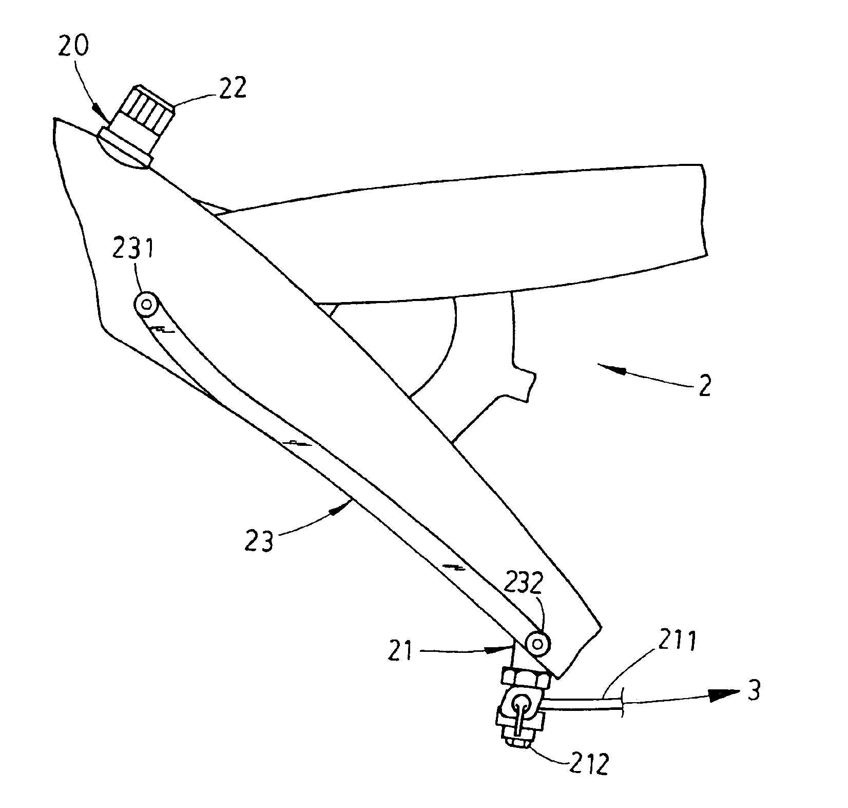
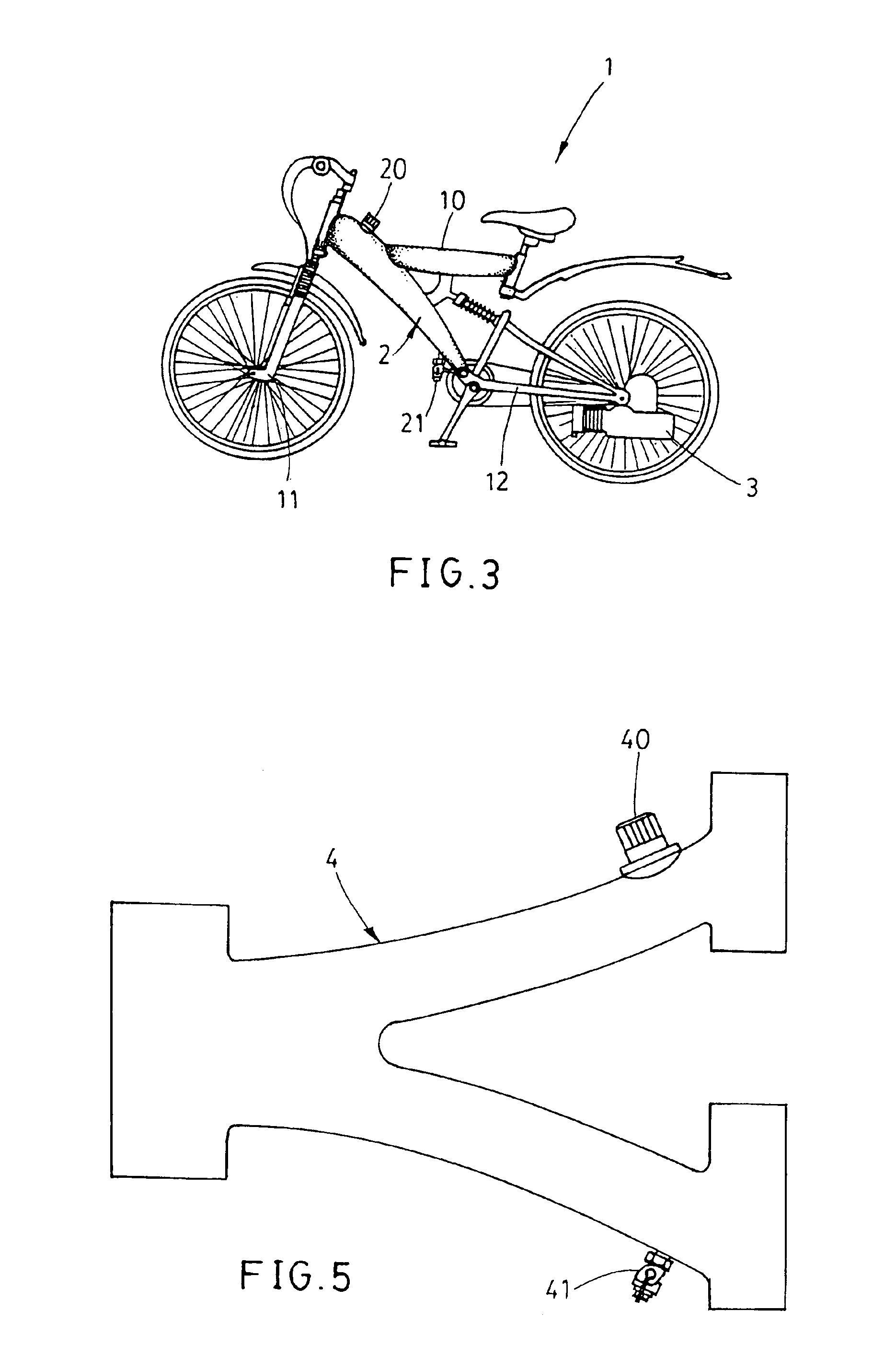
[0008]In view of the aforesaid disadvantages, the present invention aims to provide a novel fuel tank that does not affect the balance of the existing bicycle frame or cause maneuvering risk, and adopts an integrated design with the frame without external attaching problem or compromising the aesthetic appealing. The fuel container according to the invention uses and modifies the bicycle hollow frame as the fuel container. Namely the hollow bracing tubes that have a larger size and are not coupled to other structures are modified to become the fuel container. The fuel container becomes a portion of the entire frame. Hence it does not alter the balance of the frame and does not cause risky maneuvering. In addition, the frame is redesigned to maintain the original appearance and aesthetic appealing. The problem of fastening the external fuel tank also is resolved. The fuel container according to the invention, like other fuel tank designs, includes an inlet located at the top end of the container and an outlet at the bottom end of the container. A seal cap to prevent external objects from entering covers the inlet. The outlet is connected to the engine through a duct.

Problems solved by technology

While the bicycle can be used in all sorts of recreational sites, people power it, and people will feel fatigue from time to time.
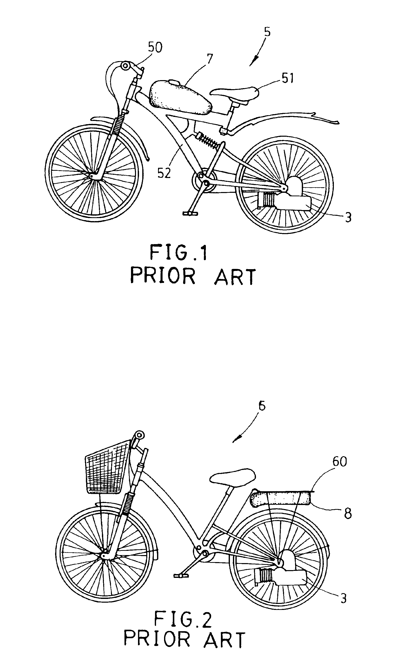
While the aforesaid fuel tank designs and mounting methods can provide fuel to drive the engine bicycle, by referring to FIGS. 1 and 2, the balanced factor for the bicycle is impaired.
With the fuel tank for other vehicles directly attached to the frame, the balance is destroyed.
This is especially true when the fuel tank is not full and shaking occurs.
In addition, the engine bicycle has acceleration effect which could make maneuvering of the bicycle difficult and result in risky situations.
Moreover, attaching the fuel tank externally has to consider stability and concern of damage to the frame.
While the external fuel tank could cause safety concern to the frame, it also impairs the aesthetic appearance and cannot achieve the appealing of integrated design.

Method used


Image

  • Fuel container for engine bicycles
  • Fuel container for engine bicycles
  • Fuel container for engine bicycles

Examples


Embodiment Construction

[0015]Refer to FIGS. 3 and 4 for an embodiment of the invention. The fuel tank for a engine bicycle 1 is located in a main frame 10 of the bicycle. The main frame 10 generally is a relatively larger frame located between a front fork 11 and a rear fork 12, and is a hollow tube. The main frame 10 in this embodiment includes a bracing tube 13 or two bracing tubes 13 and 14 that are coupled to become a fuel container 2 of the invention for the engine bicycle 1. The fuel container 2 has an inlet 20 located on the top end of the main frame 10 and covered by a screw cap 22, and an outlet 21 close to the bottom end of the main frame 10. The outlet 21 has a bottom end sealed by a drain nut 212 and is transversely connected to a fuel duct 211 at an upper location. The fuel duct 211 transports the fuel from the fuel container 2 to an engine 3. The drain nut 212 is for discharging impurities deposited on the bottom of the fuel container 2.

[0016]Referring to FIGS. 4 and 5, the fuel container 2 ...


PUM


Abstract

A fuel container for engine bicycles is formed by a selected section of a hollow frame of the engine bicycle. The fuel container has an inlet at the top end and an outlet at the bottom end thereof. The outlet is connected to a fuel line and has a drain port for discharging fuel.

Description

[0001]This Nonprovisional application claims priority under 35 U.S.C. § 119(a) on Patent Application No.(s). 091219578 filed in TAIWAN on Dec. 3, 2002, the entire contents of which are hereby incorporated by reference.BACKGROUND OF THE INVENTION[0002]1. Field of the Invention[0003]The invention relates to a fuel container for engine bicycles that is directly formed from the bicycle frame.[0004]2. Description of the Prior Art[0005]With growing popularity of recreational activities, the bicycle that was a major transportation means in the past has become fashionable again. These days many people view the bicycle as a symbol of recreation. As there are many different types of recreational activities, the bicycle also has different designs to satisfy different users, such as the regular type for the general public, and the vigorous type for crossing rugged terrain.[0006]While the bicycle can be used in all sorts of recreational sites, people power it, and people will feel fatigue from t...

Claims


Application Information

Patent Timeline
Patent Type & Authority Patents(United States)
IPC IPC(8): B62M7/12B62J35/00B62M7/00
CPCB62J35/00B62M7/12
Inventor CHEN, CHIEN-TAI
Owner FORSEN MOTOR CORP
Learn More