
Brake for DC motor

Inactive Publication Date: 2005-07-05
MITSUBISHI ELECTRIC CORP
View PDF8 Cites 4 Cited by
  • Summary
  • Abstract
  • Description
  • Claims
  • Application Information

AI Technical Summary

Benefits of technology

The present invention relates to a braking device for a DC motor that can stop the motor shaft quickly and smoothly without colliding with the stopper. The device uses a regenerative braking system and a braking force varying means to perform a smooth braking of the motor. The braking force is increased when the motor rotational speed is high. The device also predicts the position of the motor shaft and stops the braking when the motor shaft reaches the target position. The braking start position can be varied, and the device can start braking at the most suitable position. Overall, the braking device of the present invention allows for quick and smooth stopping of the DC motor.

Problems solved by technology

In particular, in a case of the DC motor having high response, there is presented a problem that the motor shaft collides with the stopper at a motor stop point to cause breakage because of an overshoot of the rotor.

Method used


Image

  • Brake for DC motor
  • Brake for DC motor
  • Brake for DC motor

Examples


embodiment 1

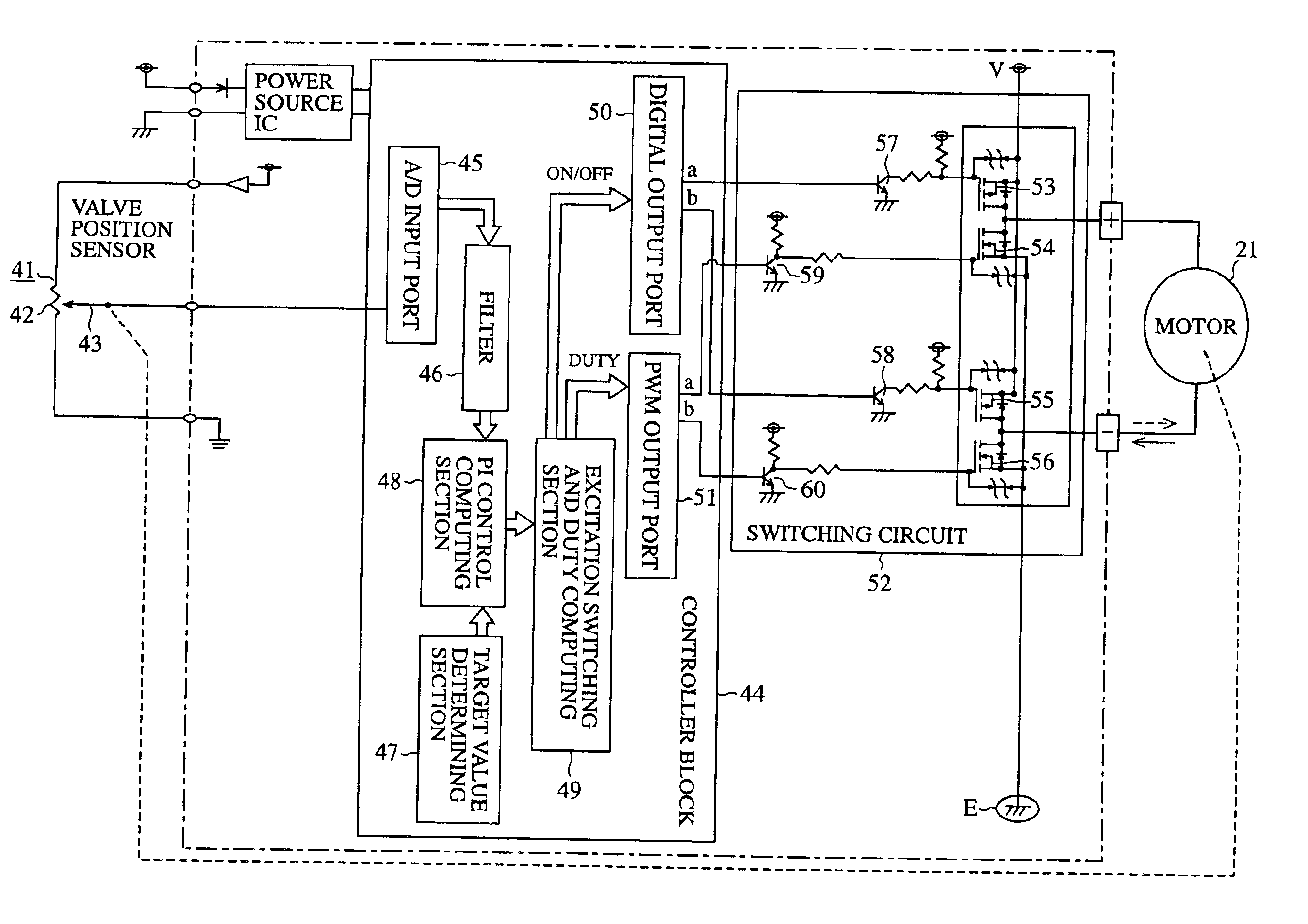
[0052]FIG. 3 is a circuit diagram to show a braking device of a DC brush motor in accordance with embodiment 1 of the invention. A reference numeral 71 denotes a deviation computing section for determining a deviation based on a present position from a filter 46 and a target value from a target value determining section 47, 72 denotes a speed computing section for determining a speed from an amount of displacement per means of time, 73 denotes an acceleration computing section for determining an acceleration from a present speed and a previous speed, 74 denotes a braking judging section (braking means) which has computation results inputted from the deviation computing section 71, the speed computing section 72 and the acceleration computing section 73 to thereby judge a start of braking and an end of braking, 75 denotes a braking duty computing section which has computation results inputted from the deviation computing section 71, the speed computing section 72 and the acceleration...

embodiment 2

[0074]FIG. 7 is a circuit diagram to show a braking device of a brushless DC motor in accordance with embodiment 2 of the invention, and the braking device has hall devices 81U, 81V, 81W for detecting a position of the rotor 23 and a switching unit 82 including a group of transistors receiving the signals of the hall devices 81U, 81V, 81W for switching the passing of a current through coils 28U, 28V, 28W, and passes a current through the coils 28U, 28V, 28W in sequence to rotate the above mentioned rotor 23 in a given direction.

[0075]The above mentioned switching unit 82 has switching devices 83U, 83V, 83W (hereinafter referred to as switch device) each of which receives the output signal from the hall devices 81U, 81V, 81W and is brought into conduction; an interrupting section 84 that receives the output signals of the switch devices 83U, 83V, 83W and outputs an interrupting signal; a signal processing block 97 that receives and processes the output signals of the above mentioned ...


PUM


Abstract

A braking device of a DC motor has a position detecting means to detect a position of a motor shaft, a rotational speed detecting means to detect a rotational speed of the motor and a braking means to generate a braking force based on a position signal and a speed signal detected by both of the means, and stops the motor shaft quickly and smoothly without making the motor shaft collide with a stopper.

Description

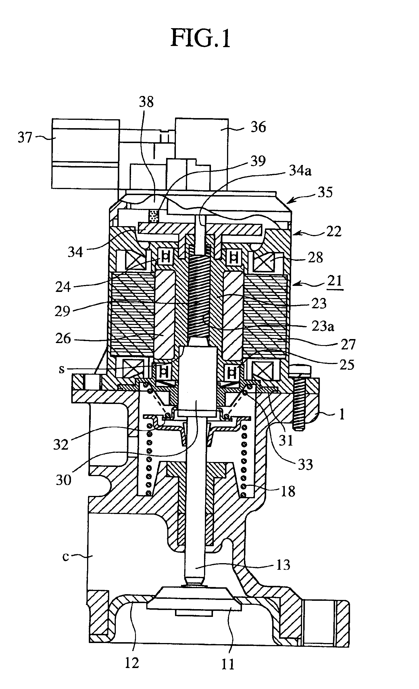
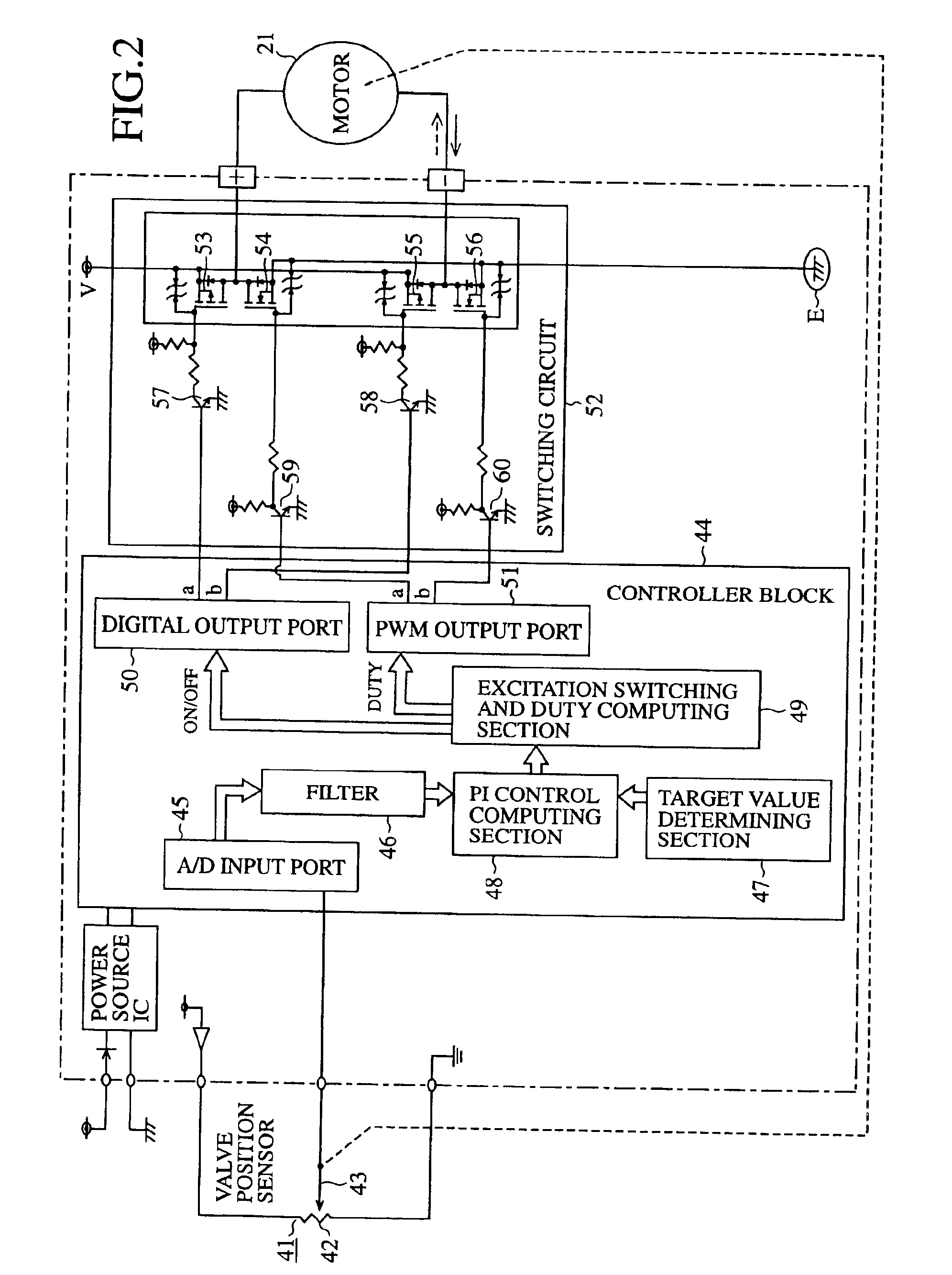
TECHNICAL FIELD[0001]The present invention relates to a braking device for a DC motor used as a driving source for driving and holding a driven body at a target position, for example, in a throttle valve, an actuator, an EGR valve and the like.BACKGROUND ART[0002]FIG. 1 is a cross sectional view to show a constitution of a current passing device of a DC motor. FIG. 2 illustrates a flow of current in the current passing device in FIG. 1. In the drawing is illustrated a longitudinal cross sectional view to show an EGR (Exhaust Gas Recirculation) valve means provided as a driving source. In FIG. 1, a reference numeral 1 denotes a valve body in which a passage communicating with an exhaust gas return passage c disposed in a recirculation system of an exhaust gas. When a control valve 11 is moved up as shown in the drawing, it is put into contact with a seat 12 to thereby close the exhaust gas return passage c and when the control valve 11 is moved down, it is separated from the seat 12 ...

Claims


Application Information

Patent Timeline
Patent Type & Authority Patents(United States)
IPC IPC(8): H02P6/00H02P6/24
CPCF02M25/0788F16K31/047H02P6/24Y02T10/121F02M26/66H02P3/08
Inventor FUJITA, YOUICHIKAWAMURA, SATOSHIMIYOSHI, SOTSUO
Owner MITSUBISHI ELECTRIC CORP
Learn More