Damper

a damper and front-end surface technology, applied in the field of dampers, can solve the problems of increasing the number of parts and assembling work, increasing the cost, etc., and achieve the effects of increasing the braking force of the damper, and reducing the number of parts

Inactive Publication Date: 2005-07-05
NIFCO INC
View PDF7 Cites 38 Cited by
  • Summary
  • Abstract
  • Description
  • Claims
  • Application Information

AI Technical Summary

Benefits of technology

[0033]Therefore, the shear resistance generated at the front-end surfaces of the projecting portions of the first and second rotors and the outer peripheral surfaces of the first and second rotors facing the front-end surfaces of the walls is increased. Therefore, a further high torque can be obtained and the braking force of the damper can be further increased.
[0034]Here, a higher torque can be obtained when the torque generating portion is positioned outwards as far as possible from the rotating center of the first and second rotors. Therefore, it is preferred that the space between the front-end surfaces of the projecting portions of the first and second rotors and the inner peripheral surface of the housing is larger than that between the front-end surfaces of the walls and the outer peripheral surfaces of the first and second rotors. Also, the walls are provided on the inner peripheral surface of the housing, so that the rotating angle of the first and second rotors can be controlled.

Problems solved by technology

However, in the damper described above, the number of parts and assembling work are increased, thereby increasing a cost.

Method used


Image

  • Damper
  • Damper
  • Damper

Examples


Embodiment Construction

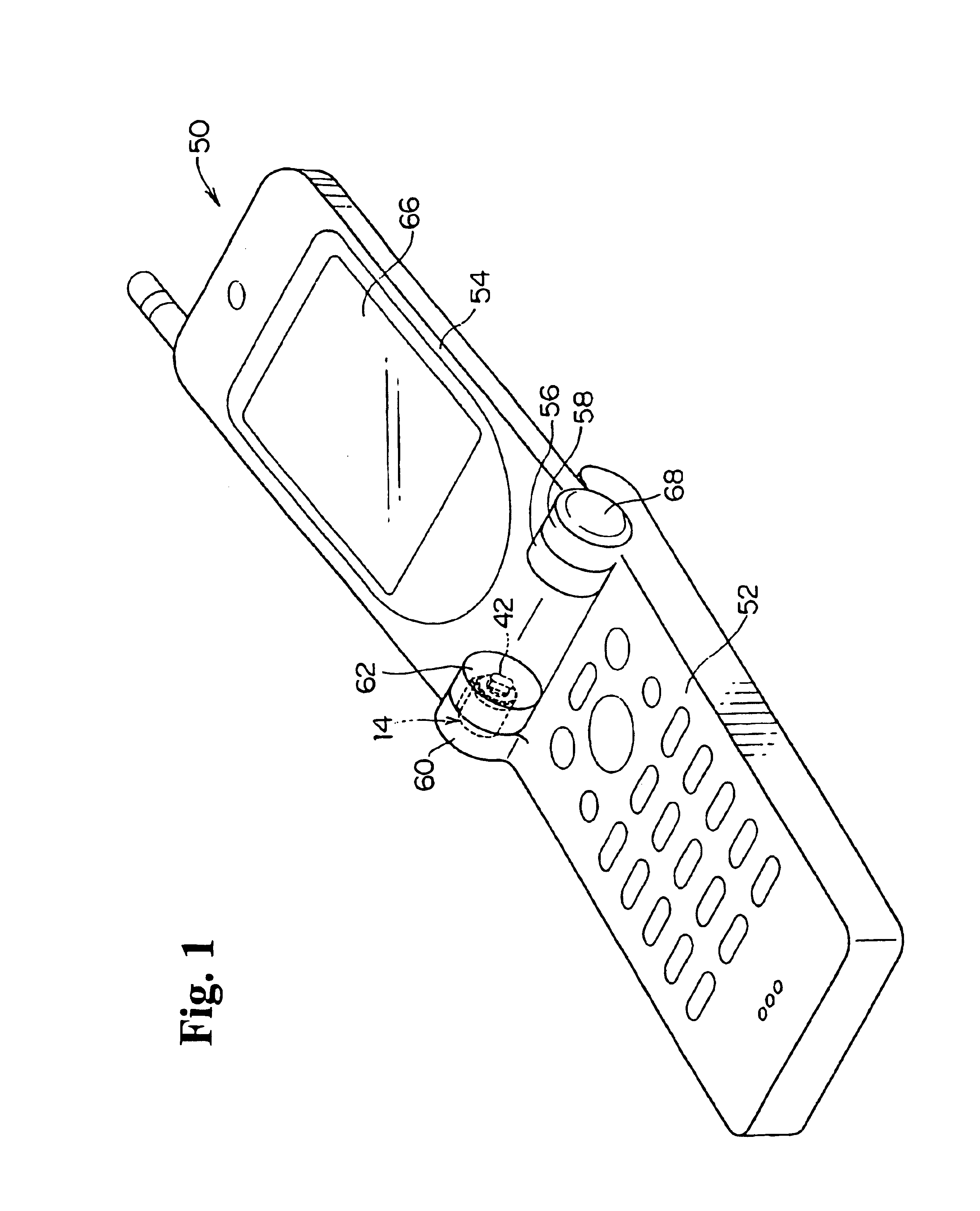
[0043]Hereunder, a damper according to an embodiment of the present invention will be described.

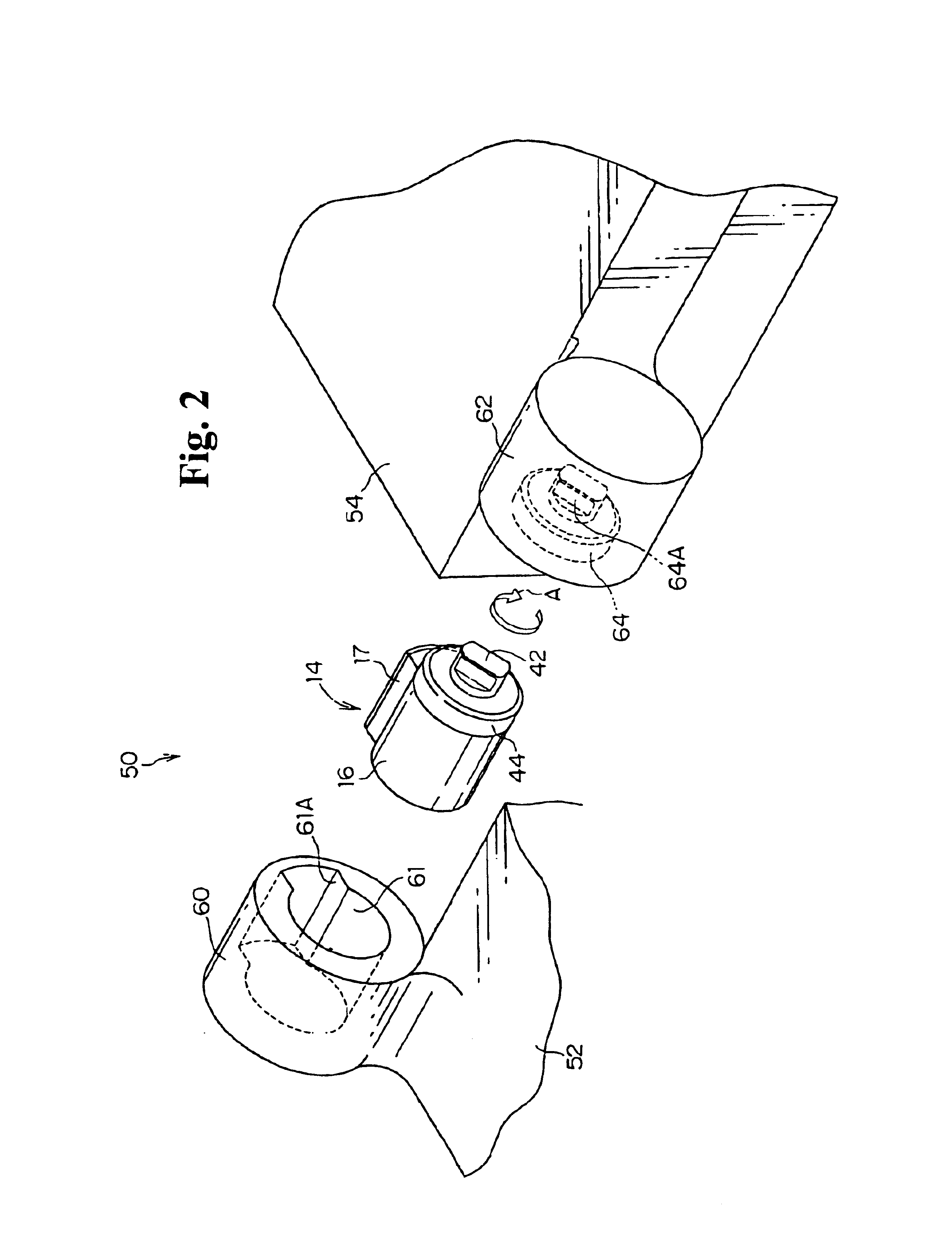
[0044]FIG. 1 shows a mobile phone 50 to which a damper 14 according to the present embodiment is applied. The mobile phone 50 is formed of a transmitting-side main portion 52 and a receiving-side main portion 54. The mobile phone 50 includes a pair of shaft portions 56, 58 and 60, 62. Therefore, the receiving-side main portion 54 can rotate with respect to the transmitting-side main portion 52, so that the mobile phone 50 is folded in a state that the receiving-side main portion 54 is closed.

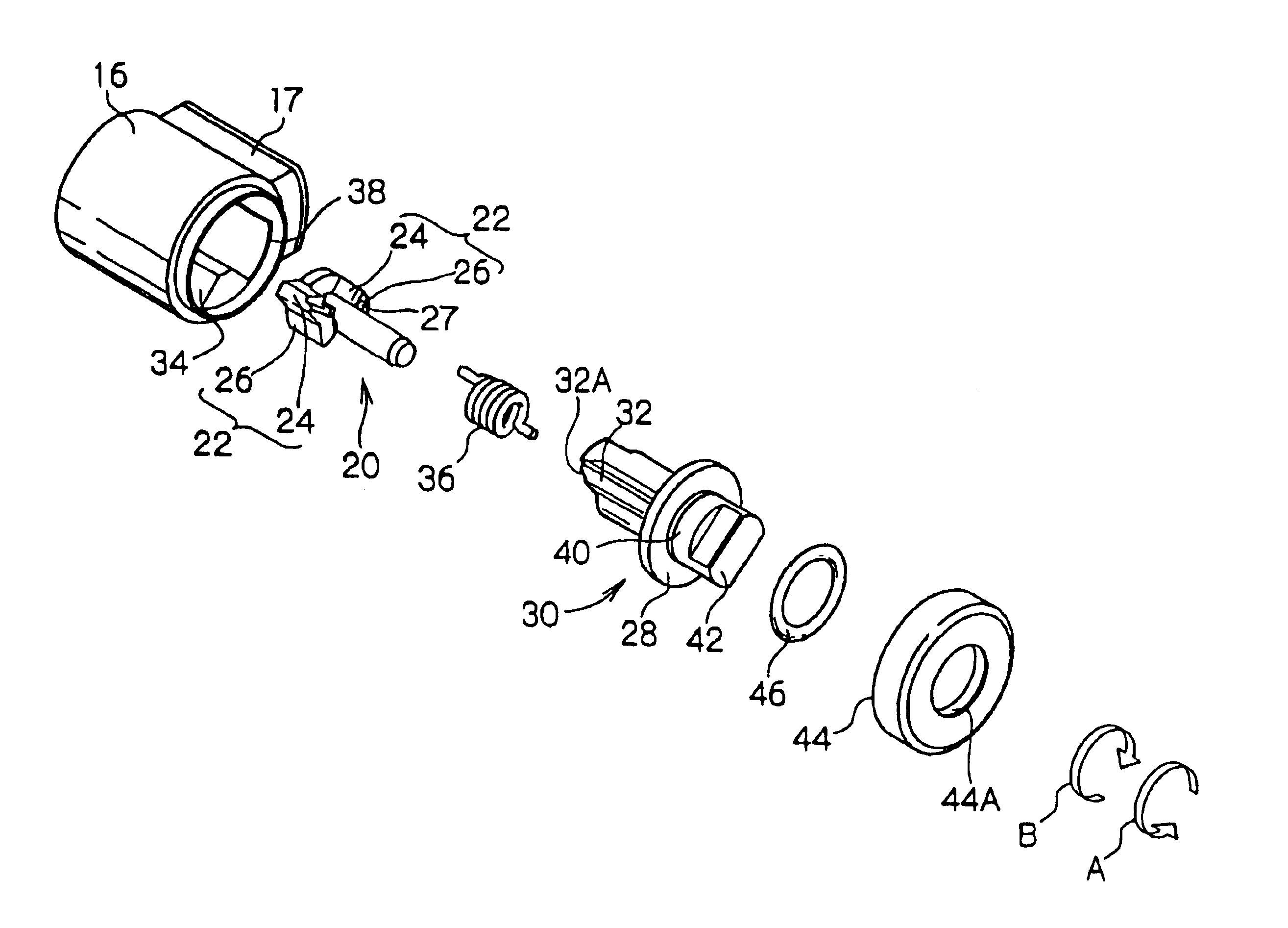
[0045]A spring, not shown, is provided at a side of the shaft portion 56, 58 for urging the receiving-side main portion 54 in a direction to open with respect to the transmitting-side main portion 52. On the other hand, a damper 14 is provided at a side of the shaft portion 60, 62, so that a braking force acts on opening of the receiving-side main portion 54.

[0046]Next, a structure of the damper 14 wi...


PUM


Abstract

A damper includes a housing having a cylindrical shape and filled with a viscous fluid, a first rotor rotatably received in the housing and having a first connecting portion formed at an end portion thereof, and a second rotor rotatably housed in the housing coaxially with the first rotor and having a second connecting portion formed at an end portion thereof. The first and second connecting portions engage to allow the first and second rotors together, and forms a space therebetween to allow the viscous fluid to pass therethrough. An elastic member urges the first connecting portion and the second connecting portion to connect together, and accumulates an elastic force in a state that the connection between the first and second connecting portions is released.

Description

BACKGROUND OF THE INVENTION AND RELATED ART STATEMENT[0001]The present invention relates to a damper.[0002]In Patent Reference No. 1, as shown in FIG. 7, a rotor 102 is disposed in a body case 100, and a silicone grease as a viscous fluid is filled in a space between the body case 100 and the rotor 102 sealed by a cap 104.[0003]The rotor 102 is provided with a clutch disc 106 to be rotatable with the rotor. Another clutch disc 108 is provided on an upper part of the clutch disc 106. Incidentally, a lid member 105 can engage the cap 104, and an engaging portion 107 projecting from the lid member 105 is exposed through a through-hole 104A formed at the center of the cap 104.[0004]Also, the clutch disc 108 is attached to a back surface of the lid member 105 so that the clutch disc 108 can rotate with the lid member 105 and move in an axial direction of the lid member 105. Further, a coil spring 110 is disposed between the back surface of the lid member 105 and the clutch disc 108 for u...

Claims


Application Information

Patent Timeline
Patent Type & Authority Patents(United States)
IPC IPC(8): F16D57/02F16D57/00F16F9/20F16F9/12
CPCF16D57/02F16F9/12Y10T16/2771Y10T16/276F16F9/20
Inventor HAYASHI, KEN
Owner NIFCO INC
Why Eureka
Try Eureka