Low profile, fine mist, finger-operated, precompression-type spray pump

a pre-compression type, spray pump technology, applied in the direction of instruments, single-unit devices, volume meters, etc., can solve the problems of slow loss of pressure from the interior of the housing, failure of the metal ball to completely close the housing bottom entrance, and decrease in relative gravity of the metal ball

Inactive Publication Date: 2005-07-05
CHONG WOO
View PDF22 Cites 7 Cited by
  • Summary
  • Abstract
  • Description
  • Claims
  • Application Information

AI Technical Summary

Benefits of technology

[0012]More specifically, the object of the invention is to provide a spray pump which can operate even with a short travel distance of a piston, allowing the height of a button spaced from a closure to be small, and which enables the pumping procedure to be performed smoothly without causing leakage by dripping at the nozzle, and which can be constructed with a small number of constituent parts, thereby significantly reducing its manufacturing cost and assembly cost, and which can also start spraying with a low empty pumping number.
[0024]Since the second valve is made of plastic material, like the housing, when the glans of the second valve comes into contact with the housing bottom entrance, the contact sealing effect is excellent, allowing almost no pressure loss in the housing's interior during the pumping procedure, compared to using a metal ball as an opening-closing means as in the prior art, which contributes to the prevention of leakage by dripping. Moreover, in the compression mode, as the poppet valve moves downward, the cylindrical body of the poppet valve being in contact with the cylindrical extending part of the poppet valve is also dragged downward, thereby the housing bottom entrance being immediately closed by the glans part of the second valve. In the release mode, as the poppet valve returns upward by an upward returning force of the spring, the housing bottom entrance is immediately opened in the same manner. Accordingly, when the pump is operated, the response speed of the glans part for closing and opening the housing bottom entrance is very fast. Due to this feature, the spray pump according to the present invention can have a relatively larger, variable volume in the same housing interior as that used in the prior art, thus pumping can be performed even with a short travel distance of the piston, which makes it possible to shorten the height of the push button spaced from the closure, and also reduce the empty pumping number.
[0025]In a preferable embodiment of the present invention, the top of the housing bottom entrance is formed to be concave in shape, and the bottom of the glans part of the second valve is formed to be convex in shape, enabling them to come into close contact with each other. Accordingly, when the second valve descends to close the housing bottom entrance in the pumping procedure, the convex portion of the glans part perfectly occludes the concave portion of the housing bottom entrance, thereby exhibiting a high sealing effect.
[0026]In another preferable embodiment of the present invention, a plurality of teeth are circumferentially formed on the outer surface of glans part of the second valve, and a plurality of grooves corresponding to the teeth are circumferentially formed on the inner surface of the housing in proximity to the housing bottom entrance, and when the teeth are engaged to the grooves, a plurality of through passages are created between them. Accordingly, the upward and downward movement of the second valve can be stably performed by the integration of these teeth and grooves, resulting in a smoother pumping action.
[0027]In another preferable embodiment of the present invention, an annular protuberance is formed on the outer surface of cylindrical body of the second valve and / or the inner surface of cylindrical extending part of the poppet valve at a position where the cylindrical body is in moveable contact with the cylindrical extending part, resulting in a further improved sealing effect

Problems solved by technology

However, the metal ball fails to entirely close the housing bottom entrance because of its spherical shape.
Furthermore, the metal ball cannot rapidly respond to the variation of pressure of the housing's interior, resulting in leakage by dripping at the nozzle, characterized by the leakage of some fluid owing to a small gap between the metal ball and the housing bottom entrance and hence the slow loss of pressure from the housing's interior.
In addition, the metal ball acts to close the housing bottom entrance by gravity upon application of a downward force to the push button, and open it in response to loss of pressure in the housing's interior upon release of the downward force; however, the density of fluid present in the housing's interior increases upon application of the downward force to the push button and thus the relative gravity of the metal ball decreases, making the rapid closing of housing bottom entrance difficult.
Therefore, owing to the pressure loss in the housing's interior and the slow response to the variation of pressure, a leakage by dripping occurs at the initial step and final step of a spraying procedure.
The spray pump in Korean patent application No. 2002-67623 and the spray pump in Korean registered utility model No. 204024 exhibit an excellent precompression function but have demerits of relatively high manufacturing cost due to the use of numerous parts.
In recent, there has been a great demand for a spray pump which exhibits a high performance and also, when mounted on a container, does not render a final product unattractive.
A large-sized push button or closure are likely to be perceived as unattractive on a final product and hence, from this viewpoint, a button and closure of small size are required.

Method used


Image

  • Low profile, fine mist, finger-operated, precompression-type spray pump
  • Low profile, fine mist, finger-operated, precompression-type spray pump
  • Low profile, fine mist, finger-operated, precompression-type spray pump

Examples


Embodiment Construction

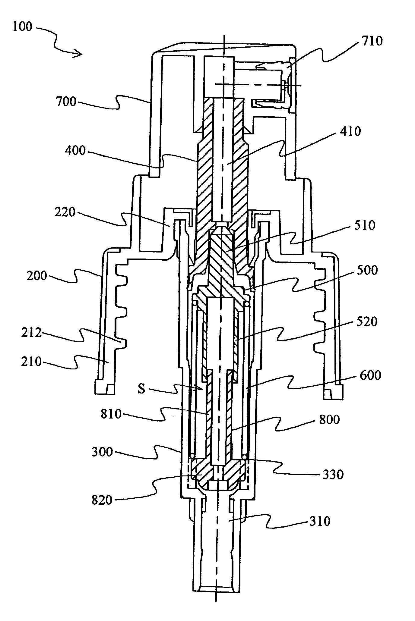
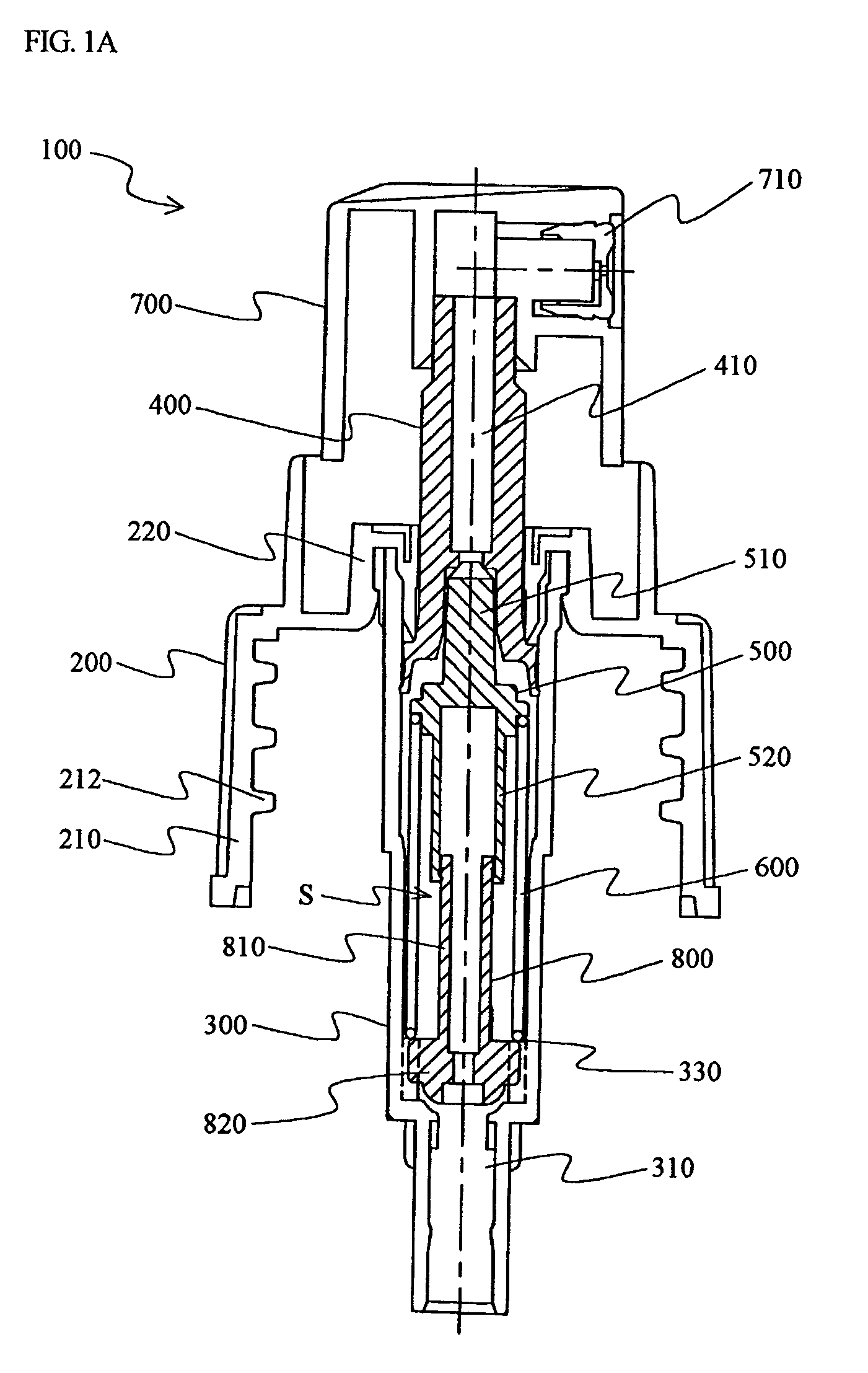
[0043]As shown below, the description refers to the relevant drawings in order to describe the present invention more clearly, and such description is not to be interpreted as limiting the present invention in any way.

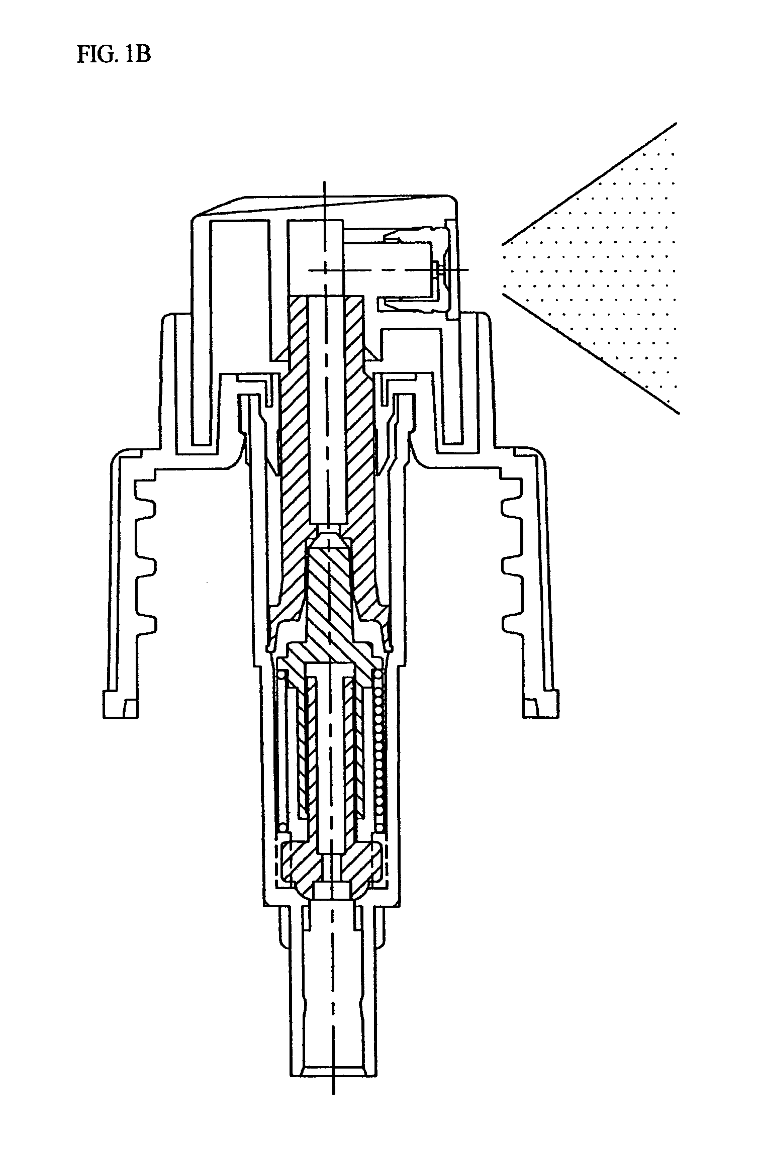
[0044]FIG. 1A shows the longitudinal section view of a spray pump according to one embodiment of the present invention being in the release mode (more particularly, rest mode), and FIG. 1B shows the longitudinal section view of the spray pump being in the compression mode (more particularly, spray mode).

[0045]Referring to FIG. 1A, a spray pump 100 comprises, a closure 200 for securely holding the pump 100 to the neck of a container (not shown); a housing 300 for guiding the flow of the fluid to be sprayed, and which is configured as a multi-step structure; a piston 400 being moveable upwardly and downwardly along the inner surface of the housing 300, and which has a vertical duct 410 formed along the central axis thereof; a poppet valve 500 for closing and opening the ...


PUM


Abstract

The present invention relates to a low profile, fine mist, finger-operated, precompression-type spray pump, and more particularly to a spray pump provided with a second valve of the novel structure being moveable between a poppet valve and a bottom entrance of housing, to precompress the fluid as a liquid content and then spray, whereby the spray pump can be operated even with a short travel distance of a piston, which enables to make the height of a push button spaced from a closure to be shorter than the existing ones, and the pumping process can be smoothly performed without leakage and can also be started with small empty pumping numbers. In addition, the spray pump according to the present invention is constructed with small numbers of constituent parts, resulting in the significant reduction of manufacturing cost and assembly cost.

Description

FIELD OF THE INVENTION[0001]The present invention relates to a low profile, fine mist, finger-operated, precompression-type spray pump, and more particularly to a spray pump provided with a second valve having a novel structure being moveable between a poppet valve and a bottom entrance of a housing, to precompress a liquid to be sprayed, whereby the spray pump can be operated even with a short travel distance of a piston, which enables the height of a push button spaced from a closure to be shorter than in existing spray pumps, and the pumping process to be smoothly performed without causing dripping of the liquid at a nozzle and to be initiated with a small number of pumping actions under the condition that the housing is empty (“empty pumping number”). In addition, the spray pump according to the present invention is constructed with a small number of constituent parts, resulting in the significant reduction of its manufacturing cost and assembly cost.[0002]Spray pumps which nebu...

Claims


Application Information

Patent Timeline
Patent Type & Authority Patents(United States)
IPC IPC(8): B05B9/04B05B11/00G01F11/06G01F11/02
CPCB05B11/3018B05B11/3063B05B11/1018B05B11/1063B05B11/00
Inventor LEE, CHUNG KEE
Owner CHONG WOO
Why Eureka
Try Eureka