Coupling for coaxial connection of fluid conduits

a fluid conduit and coaxial connection technology, applied in the direction of hose connection, coupling, transportation and packaging, etc., can solve the problems of end product being heavy and quite costly, joining forms eventually leaking, ultimate failure of the coupling, etc., to achieve strong resistance, not hindering the sealing of the joint or o-ring performance, and high operating pressure

Inactive Publication Date: 2005-07-05
HALLA CLIMATE CONTROL CANADA
View PDF24 Cites 50 Cited by
  • Summary
  • Abstract
  • Description
  • Claims
  • Application Information

AI Technical Summary

Benefits of technology

[0008]The object of the present invention is to provide an improved coupling which overcomes some or all of the disadvantages of known prior art couplings. Desirably the improved coupling provides for easy interconnection of fluid conduits in end-to-end relationship while ensuring sealing integrity. The coupling can be pre-assembled to the tube ends prior to their union and desirably is capable of sustaining high operating pressures within the conduits. Furthermore desirably the coupling will provide strong resistance against skewing or axial misalignment of the tubes after assembly, will not hinder the sealing of the joint or O-ring performance, and will be reusable.

Problems solved by technology

These are bulky in size and may require extensive brazing or may have multiple components (e.g. springs, collars or bolts) which result in the end product being heavy and quite costly.
Furthermore many such couplings that are currently available do not ensure sufficient concentricity between the ends of the conduits so that the joined forms will eventually leak.
However this coupling is not capable of sustaining the concentricity of the tube axes against shifting, so that leakage will eventually result.
Furthermore high pressure forces within the tubes produce loads which are concentrated on the snaps and the hinge, potentially causing ultimate failure of the coupling.
However this coupling requires excessive force to interconnect the tubes, and under high pressure excessive forces are transferred to the snaps.

Method used


Image

  • Coupling for coaxial connection of fluid conduits
  • Coupling for coaxial connection of fluid conduits
  • Coupling for coaxial connection of fluid conduits

Examples


Embodiment Construction

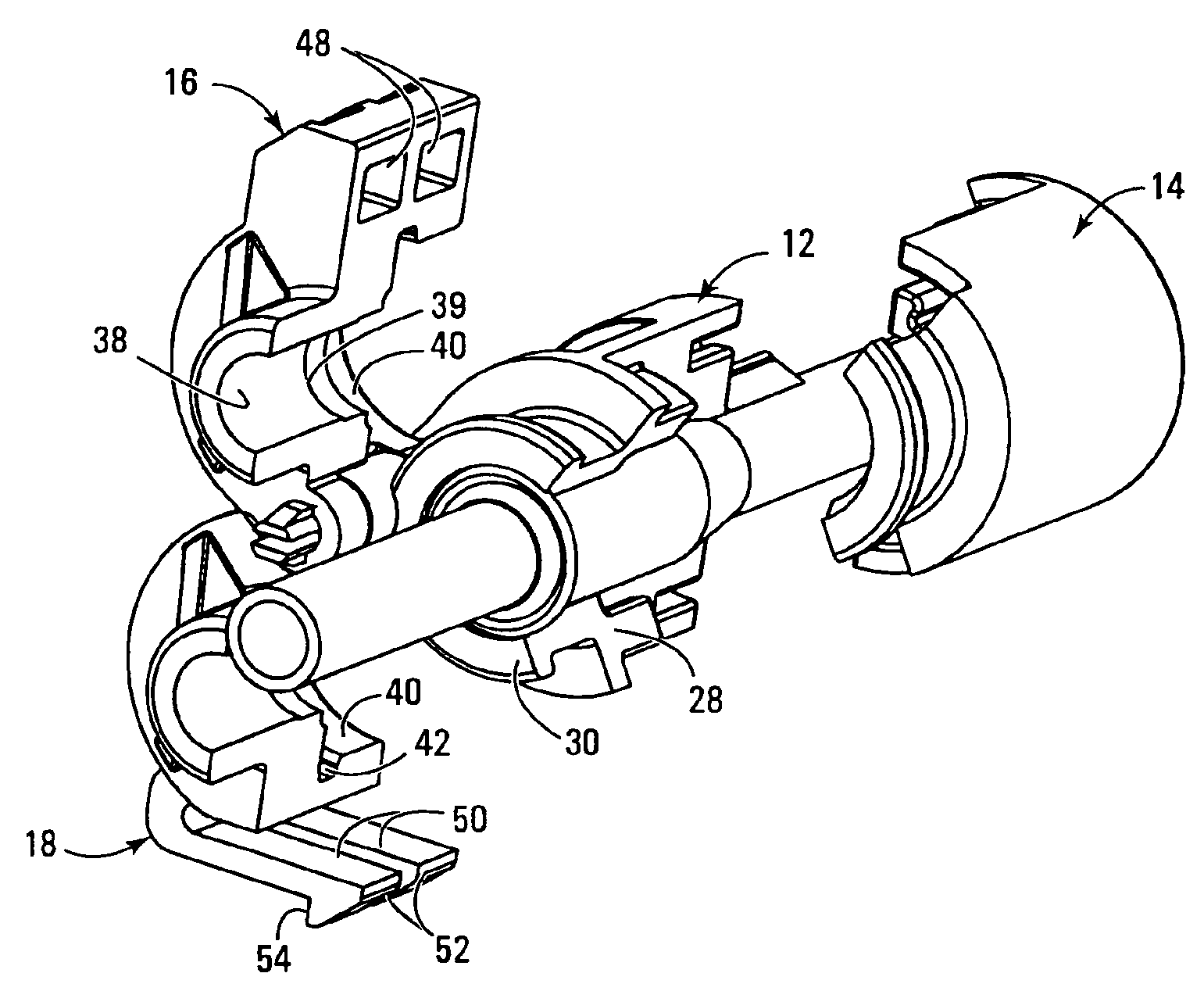
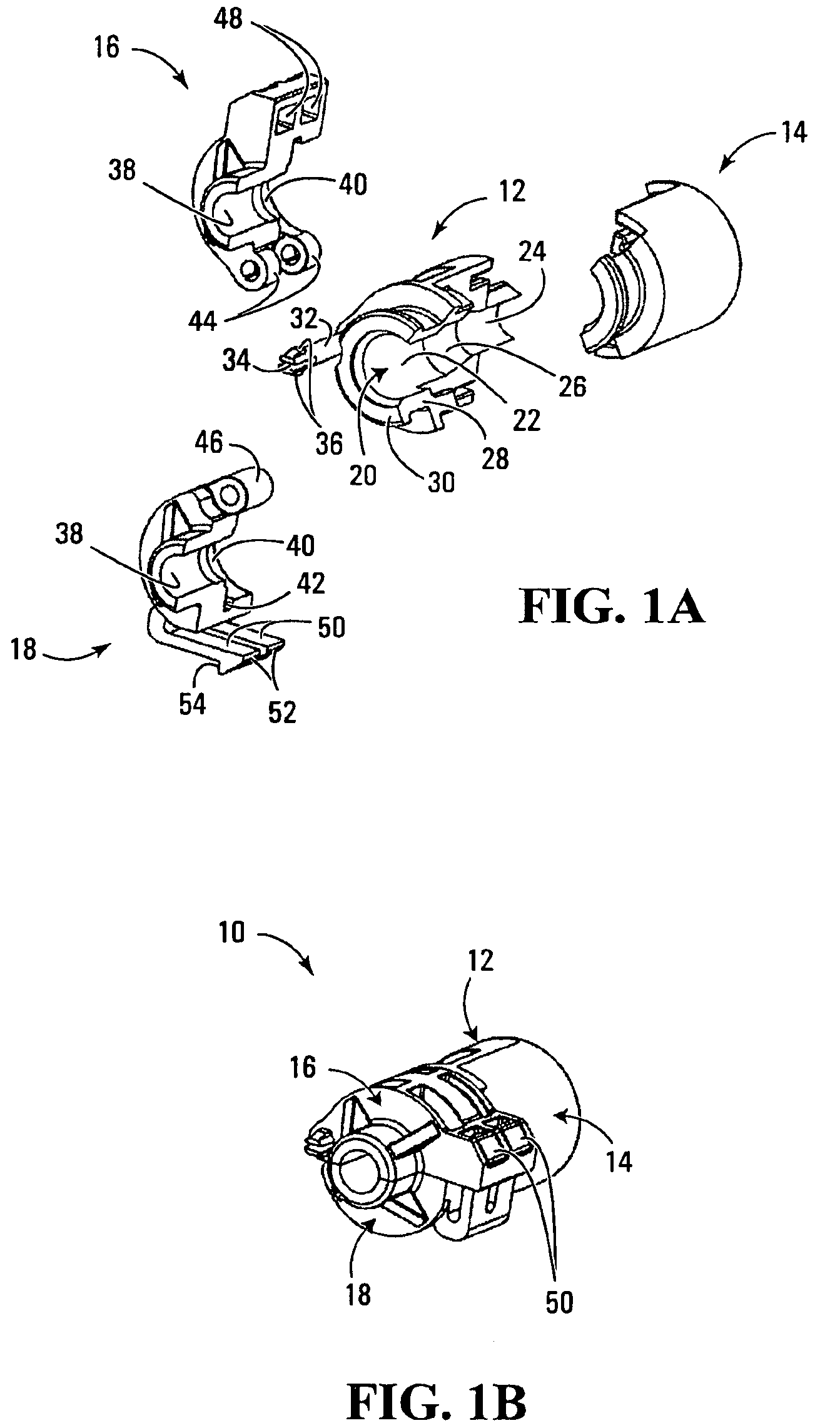
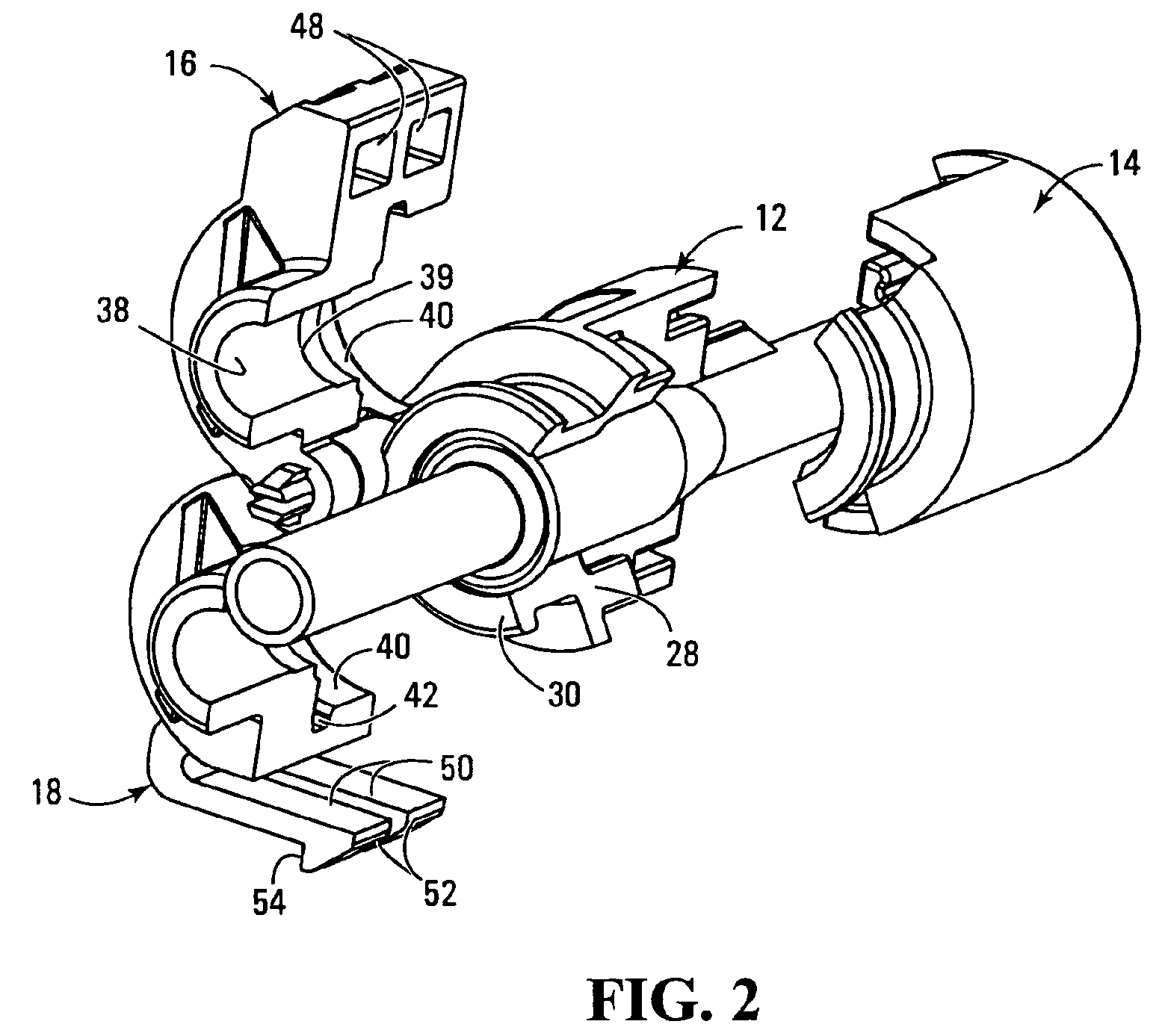
[0031]The coupling indicated at 10 in FIG. 1B is shown in compact condition with the components interengaged as they would be when the coupling is in operation. The individual components however are shown more clearly in the exploded view of FIG. 1A and will be seen to comprise four principal elements namely a base 12, a base retainer 14, and first and second clamping arms 16, 18.

[0032]The base has a stepped cylindrical bore 20 having a larger diameter section 22 and a smaller diameter section 24 joined through a tapered frusto conical portion 26.

[0033]All four of the components 12, 14, 16 and 18 are fabricated as injection molded plastic parts, suitable materials being polyaramid (nylon) glass filled, polyurethane, styrene / acrylonitrile copolymer (crystalline or amorphous resins).

[0034]As is seen in FIG. 1A the base has a thick peripheral wall that surrounds the stepped cylindrical bore over most of the length of the latter. However at one end the base has a cylindrically curved tu...


PUM


Abstract

A coupling is designed for sealingly connecting two fluid conduits such as automotive fluid lines in axial end-to-end relationship. The conduits have respective telescopically interengaging male and female end sections and the coupling comprises a base member to be carried on one of the fluid conduits and a retaining structure mounted on the base member and having two C-shaped arms which can be interconnected around the other conduit end section. A releasable lock acts between the arms to lock the retaining structure in engagement. In the locked condition the axially oriented abutment surfaces in the retaining structure engage peripheral shoulders on the conduits to prevent axial separation of the latter. The coupling can be fabricated from integral plastic components and preferably includes a guard arrangement to shield the releasable lock against inadvertent disengagement.

Description

BACKGROUND OF THE INVENTION[0001]a) Field of Invention[0002]This invention relates to a new or improved coupling for sealingly interconnecting two fluid conduits in axial end-to-end relationship.[0003]b) Description of the Prior Art[0004]Automotive fluid lines are typically joined by metal connectors. These are bulky in size and may require extensive brazing or may have multiple components (e.g. springs, collars or bolts) which result in the end product being heavy and quite costly. Furthermore many such couplings that are currently available do not ensure sufficient concentricity between the ends of the conduits so that the joined forms will eventually leak.[0005]Automotive fluid line couplings currently employed are disclosed in U.S. Pat. Nos. 5,647,612 and 6,155,607.[0006]The couplings shown in U.S. Pat. No. 5,647,612 is fabricated from plastic and includes as a retaining feature an over-molded metal component. However this coupling is not capable of sustaining the concentricity ...

Claims


Application Information

Patent Timeline
Patent Type & Authority Patents(United States)
IPC IPC(8): F16L37/50F16L37/00F16L23/00F16L27/12F16L23/04F16L21/06
CPCF16L21/06F16L23/04F16L37/1225
Inventor TREVERTON, ANDREW CLAREPARK, LEONARD J.FOSTER, STEVE ROGERMANN, EDWARD ALEXANDER
Owner HALLA CLIMATE CONTROL CANADA
Why Eureka
Try Eureka