Electric actuator to produce a predetermined force

a predetermined force, electric actuator technology, applied in the direction of electric programme control, box making operation, program control, etc., can solve the problem of reducing the throughput of the heat sealing station b>

Active Publication Date: 2005-07-05
RIVER SOLUTIONS
View PDF2 Cites 36 Cited by
  • Summary
  • Abstract
  • Description
  • Claims
  • Application Information

AI Technical Summary

Problems solved by technology

This reduces the throughput of the heat sealing station 10.

Method used


Image

  • Electric actuator to produce a predetermined force
  • Electric actuator to produce a predetermined force
  • Electric actuator to produce a predetermined force

Examples


Embodiment Construction

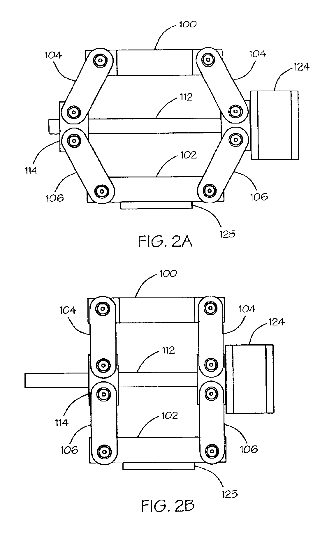
[0020]FIGS. 2A and 2B show an electric actuator according to the present invention. The actuator includes a first plate 100 and a second plate 102 that is substantially parallel to the first plate 100. A linkage system couples the first plate 100 to the second plate 102. The linkage system includes at least a first link 104 pivotally connected to a second link 106. It will be appreciated that the linkage system may be replicated one or more times to provide stability in the linkage between the first plate 100 and the second plate 102 and to increase the strength of the linkage system. If multiple linkage systems are used, all the linkage systems will function in unison and, for the purposes of this description, will be described as a single linkage system.

[0021]An electric motor 124 is coupled to a screw 112 such that the electric motor is capable of rotating the screw. The electric motor 124 and the screw 112 are coupled to the two links 104, 106 of the linkage system with the scre...


PUM

PropertyMeasurementUnit
forceaaaaaaaaaa
movementaaaaaaaaaa
forcesaaaaaaaaaa

Abstract

An electric actuator Includes a first plate and a substantially parallel second plate. A linkage system couples the first plate to the second plate such that moving the linkage system toward an over-center position causes the second plate to move away from the first plate. An electric motor is coupled to the linkage system to move the linkage system toward the over-center position. A force transducer is coupled to the actuator to produce a force signal responsive to a force produced by the actuator. A control system is coupled to the electric motor and the force transducer to provide a control signal to the electric motor to move the linkage system to a position that was determined by the control system in response to the force signal in a previous movement of the linkage system.

Description

BACKGROUND OF INVENTION[0001]The invention relates to linear actuators. In particular, the invention relates to an electrical actuator that provides a linear motion and produces a predetermined force at the end of the outward extension of the actuator.[0002]Linear actuators are used to move machine parts along a straight path. For example, a linear actuator may be used to move a first plate toward a fixed second plate to produce a pressing or clamping action. It may be desirable for the actuator to advance and produce a predetermined force.[0003]For example, fabrication of articles of manufacture from plastic films, such as bags and pouches, generally requires the welding together of two or more plastic films or sheets to form seams or closures. Plastic films may also be heat sealed to unlike materials such as paperboard or metal foils. Heat sealing or welding may be accomplished by pressing a heated die or seaming iron with the pattern of the required seams or closures against the ...

Claims


Application Information

Patent Timeline
Patent Type & Authority Patents(United States)
IPC IPC(8): G05B19/40
CPCG05B19/40B29C66/92211B30B1/103B29C65/18B29C66/1122B29C66/43B29C66/8221B29C66/824B29C66/8322B29C66/8511B29C66/92611B29C66/9292B31B1/00B29C66/961B29C66/81457B29C66/8246B29C66/8432B31B2219/145B31B2219/6038B31B2219/95G05B2219/42092B31B70/16B31B70/642B31B70/006
Inventor WILKES, KENNETH R.BEARD, S. CLARK
Owner RIVER SOLUTIONS
Why Eureka
Try Eureka