Power supply system and method thereof

Active Publication Date: 2005-07-05
FUJI ELECTRIC CO LTD
View PDF4 Cites 18 Cited by
  • Summary
  • Abstract
  • Description
  • Claims
  • Application Information

AI Technical Summary

Benefits of technology

[0011]Another aspect of the present invention is a method of controlling the power supply system. The method includes outputting a voltage to the load by inputting the first signal to the control circuit thereof to turn ON and OFF the first and second switching elements without overlapping ON-periods of the first and second switching elements, and turning ON the second switching element m times in a stepping period during which the first switching element turns ON n times, wherein n is a predetermined integer, and m is an integer between any of zero and n that increases in every stepping period. The method further includes outputting a voltage to the load by inputting the second selection signal to the series regulator.

Problems solved by technology

For example, a DC-DC converter that steps down the voltage by means of PWM control exhibits low power efficiency when the loading is light and high power efficiency when the loading is heavy.
This is due to driving losses generated at the ON-OFF operation of semiconductor switches in the DC-DC converter.
As described above, the problem with the conventional power supply system is that when the power source is changed over from the series regulator 50 to the DC-DC converter 40, the ON-period of the transistor Q4 becomes excessively large, causing a backward current flow through the transistor Q4 to the ground, resulting in drop in the output voltage.

Method used


Image

  • Power supply system and method thereof
  • Power supply system and method thereof
  • Power supply system and method thereof

Examples


Embodiment Construction

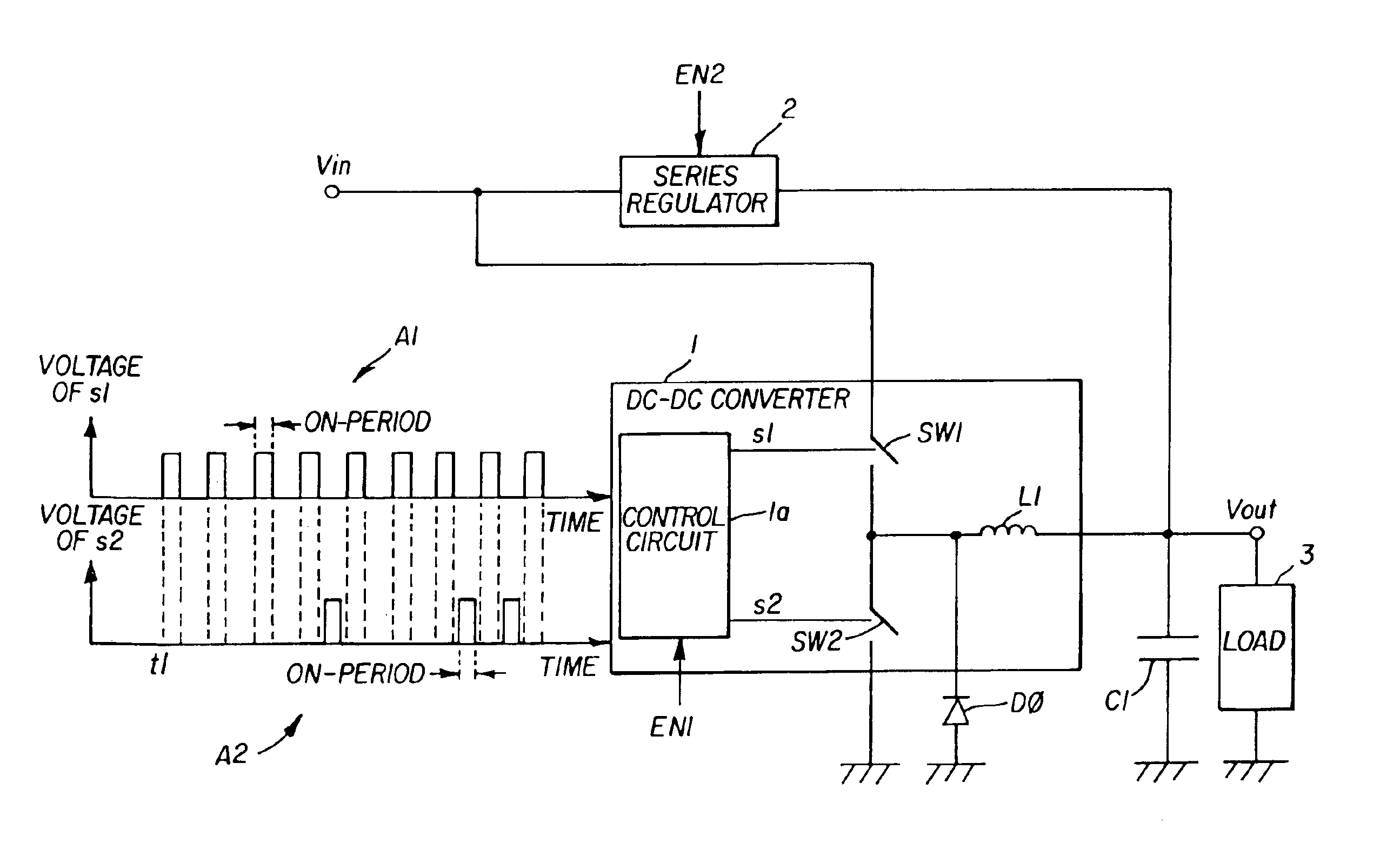
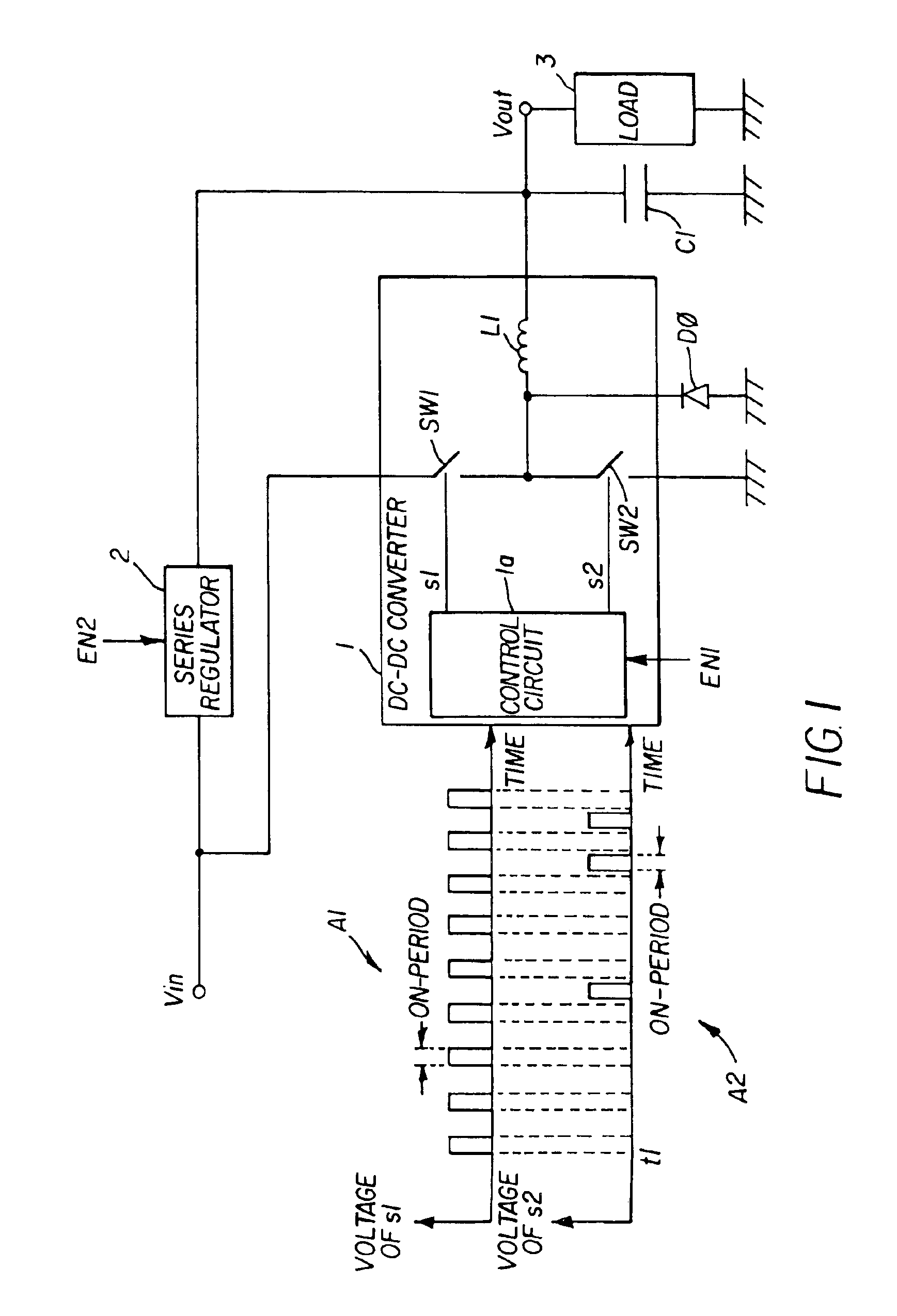
[0020]FIG. 1 shows a principle of a power supply system according to the present invention. The power supply system comprises a DC-DC converter 1 and a series regulator 2. The DC-DC converter 1 includes a control circuit 1a, switching elements SW1 and SW2, a free wheeling diode D0, and an inductor L1. The FIG. 1 also shows voltage waveforms A1 and A2 of switching signals s1 and s2 that are output from the control circuit 1a. The DC-DC converter 1 and the series regulator 2 are connected parallel to each other. Output terminals of the DC-DC converter 1 and the series regulator 2 connect to a capacitor C1 and a load 3. The DC-DC converter 1 steps down the input voltage Vin and outputs to the load 3 when a first selection signal EN1 is input thereto. The series regulator 2 steps down the input voltage Vin and outputs to the load 3 when a second selection signal EN2 is input thereto.

[0021]The first selection signal EN1 or the second selection signal EN2 is input to the DC-DC converter 1...


PUM


Abstract

A power supply system prevents the output voltage from dropping during the changeover of the power source from a series regulator to a DC-DC converter. The power supply system has two types of power sources, a DC-DC converter and a series regulator that are connected parallel to each other. The first switching element of the DC-DC converter transfers the input voltage to the load. The second switching element connects the load to the ground. The control circuit turns ON and OFF the first and second switching elements on receipt of a first selection signal so that the number of turn-ONs of the second switching element gradually increases. This suppresses the current from flowing backward through the second switching element SW2 to the ground while the power source is changing over, preventing drop in the output voltage.

Description

BACKGROUND[0001]A power supply mounted on an electronic apparatus steps down an external voltage to a level appropriate for the electronic circuit in the apparatus. Power efficiency of some of such power supplies varies depending on the loading condition of the output terminal of the power supply. For example, a DC-DC converter that steps down the voltage by means of PWM control exhibits low power efficiency when the loading is light and high power efficiency when the loading is heavy. This is due to driving losses generated at the ON-OFF operation of semiconductor switches in the DC-DC converter. On the other hand, a series regulator performs at constant power efficiency independently of the loading.[0002]There are known power supply systems that exchange a power source between a DC-DC converter and a series regulator corresponding to the loading, as disclosed in Japanese Unexamined Patent Application Publication No. H11-341797 and No. 2002-112457. When the load connected to the po...

Claims


Application Information

Patent Timeline
IPC IPC(8): H02M3/04H02M3/158
CPCH02M3/1584H02M3/1588Y02B70/1466Y02B70/10
Inventor KATAYAMA, YASUSHI
Owner FUJI ELECTRIC CO LTD
Why Eureka
Try Eureka