
Eddy current probe having sensing elements defined by first and second elongated coils and an associated inspection method

a technology sensing elements, applied in the field of eddy current probes, can solve the problems of inconvenient operation, inconvenient maintenance, and inability to meet the requirements of routine field inspection, and achieve the effect of reducing fatigu

Inactive Publication Date: 2005-07-05
THE BOEING CO
View PDF24 Cites 80 Cited by
  • Summary
  • Abstract
  • Description
  • Claims
  • Application Information

AI Technical Summary

Benefits of technology

[0008]An improved eddy current probe and associated method of inspecting an object are provided by the present invention. The eddy current probe of the present invention is capable of generating a two-dimensional image of at least a portion of a structure under inspection such that cracks, corrosion, dents or damage attributable to lightning strikes, fire or the like, may be readily determined. The eddy current probe and associated inspection method of one embodiment may generate the two-dimensional image in real time, thereby eliminating the requirement of tracking the position of the probe relative to the surface of the structure under inspection as required by conventional manual eddy current probes. Thus, the eddy current probe of the present invention may be moved more freely over a structure than conventional manual eddy current inspection systems. Additionally, the generation of a two-dimensional image of the structure under inspection in real time by the eddy current probe and the inspection method of one embodiment of the present invention permits the structure to be inspected more rapidly than conventional systems, thereby reducing any fatigue otherwise experienced by a technician.

Problems solved by technology

While automated eddy current inspection systems provide for relatively fast and accurate inspections, the automated systems are quite expensive.
In many cases, structures must be inspected in the field since, for example, it may not be feasible or it may be too expensive and / or time-consuming to transport the structure to an offsite laboratory for inspection.
In these instances, the automated eddy current inspection systems may prove to be too bulky for routine field inspections.
Additionally, the use of an automated eddy current inspection system in the field may further be hampered by the inability of an automated system to be powered by a local power supply, such as batteries, and the automated eddy current inspection system may, instead, need to be connected to a remote power supply via bulky power cables.
Thus, a two-dimensional image of the structure cannot be created in real time.
Thus, any slippage between the position encoder and the underlying structure would render any subsequently obtained measurements of the current induced in the coil(s) inaccurate since the relative position upon the surface of the structure at which those measurements were obtained cannot be accurately defined.
Moreover, since the generation of the two-dimensional image relies upon the movement of the sensor in one direction, the movement of the eddy current sensor in any other direction would also prevent a two-dimensional image of the structure from being properly created.
Thus, the manual scanning of structures with a conventional eddy current sensor is time-consuming, labor-intensive and prone to human error.
Additionally, manual scanning of an eddy current sensor over the surface of a structure may fatigue the technician.

Method used


Image

  • Eddy current probe having sensing elements defined by first and second elongated coils and an associated inspection method
  • Eddy current probe having sensing elements defined by first and second elongated coils and an associated inspection method
  • Eddy current probe having sensing elements defined by first and second elongated coils and an associated inspection method

Examples


Embodiment Construction

[0020]The present inventions now will be described more fully hereinafter with reference to the accompanying drawings, in which some, but not all embodiments of the invention are shown. Indeed, these inventions may be embodied in many different forms and should not be construed as limited to the embodiments set forth herein; rather, these embodiments are provided so that this disclosure will satisfy applicable legal requirements. Like numbers refer to like elements throughout.

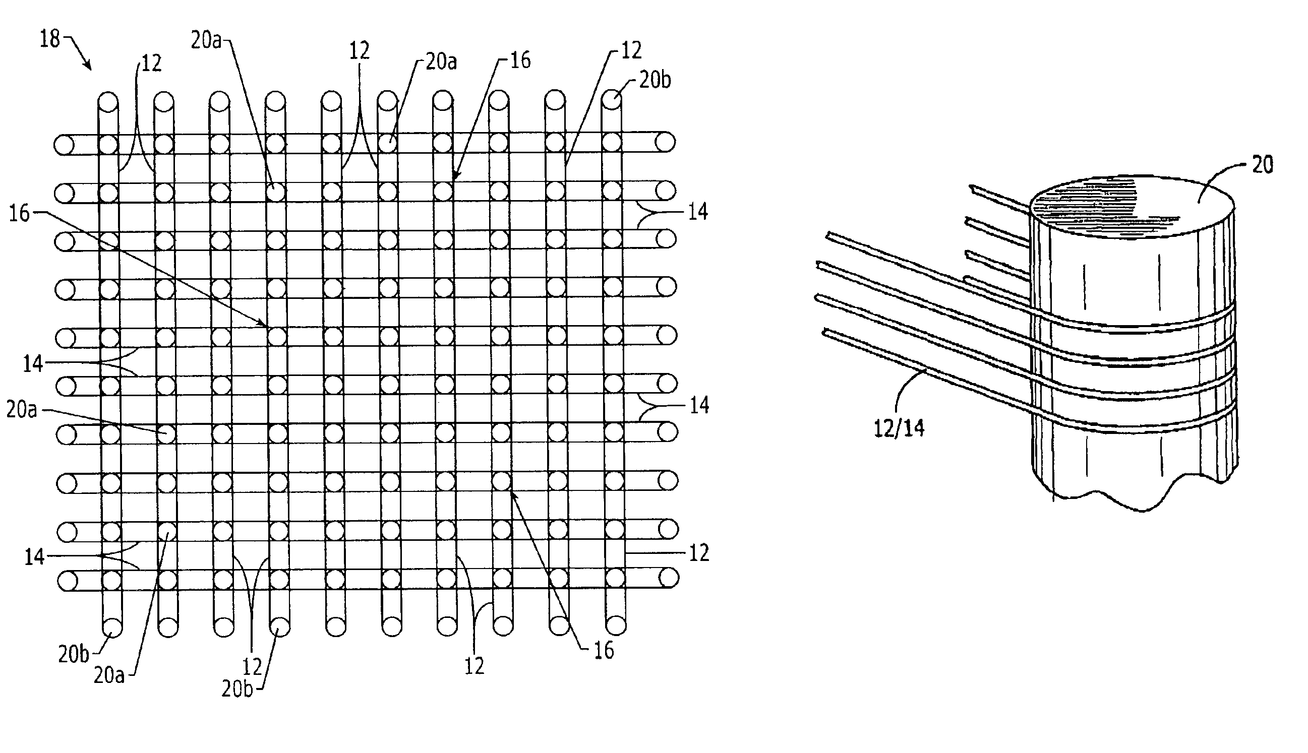
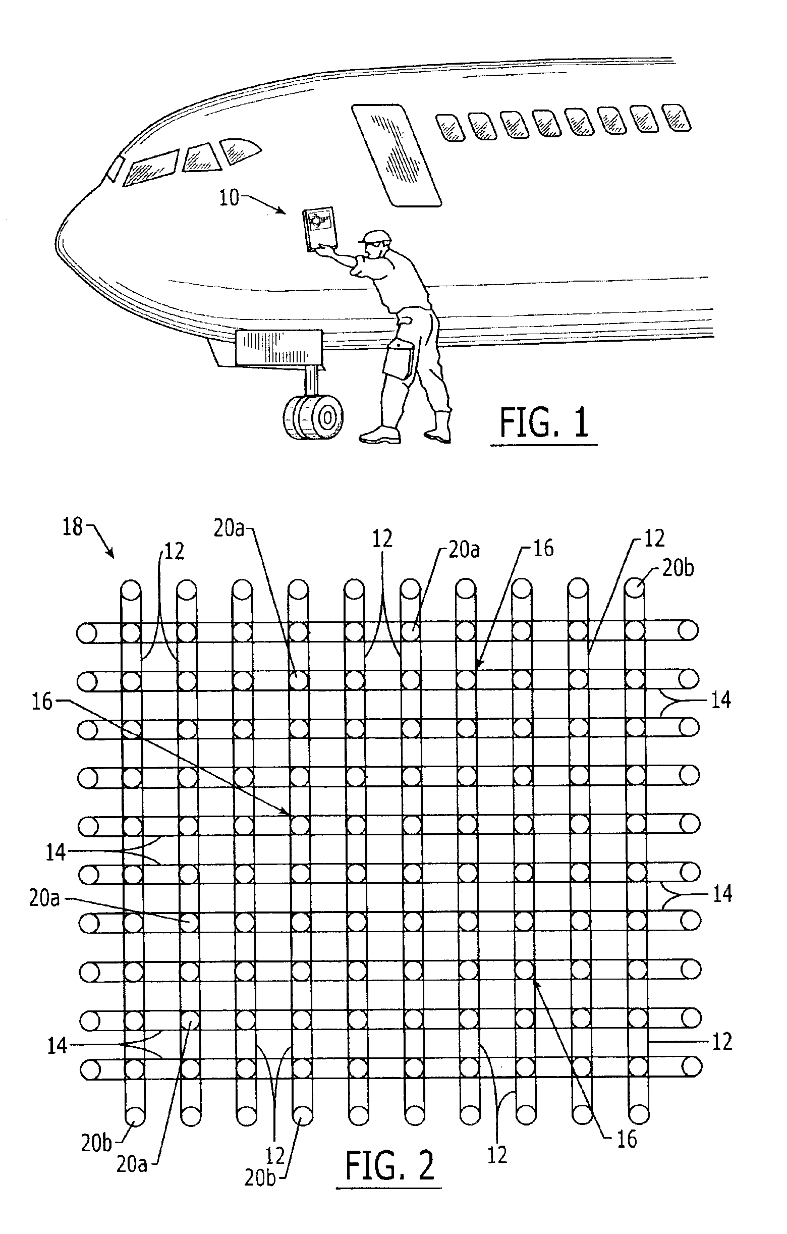
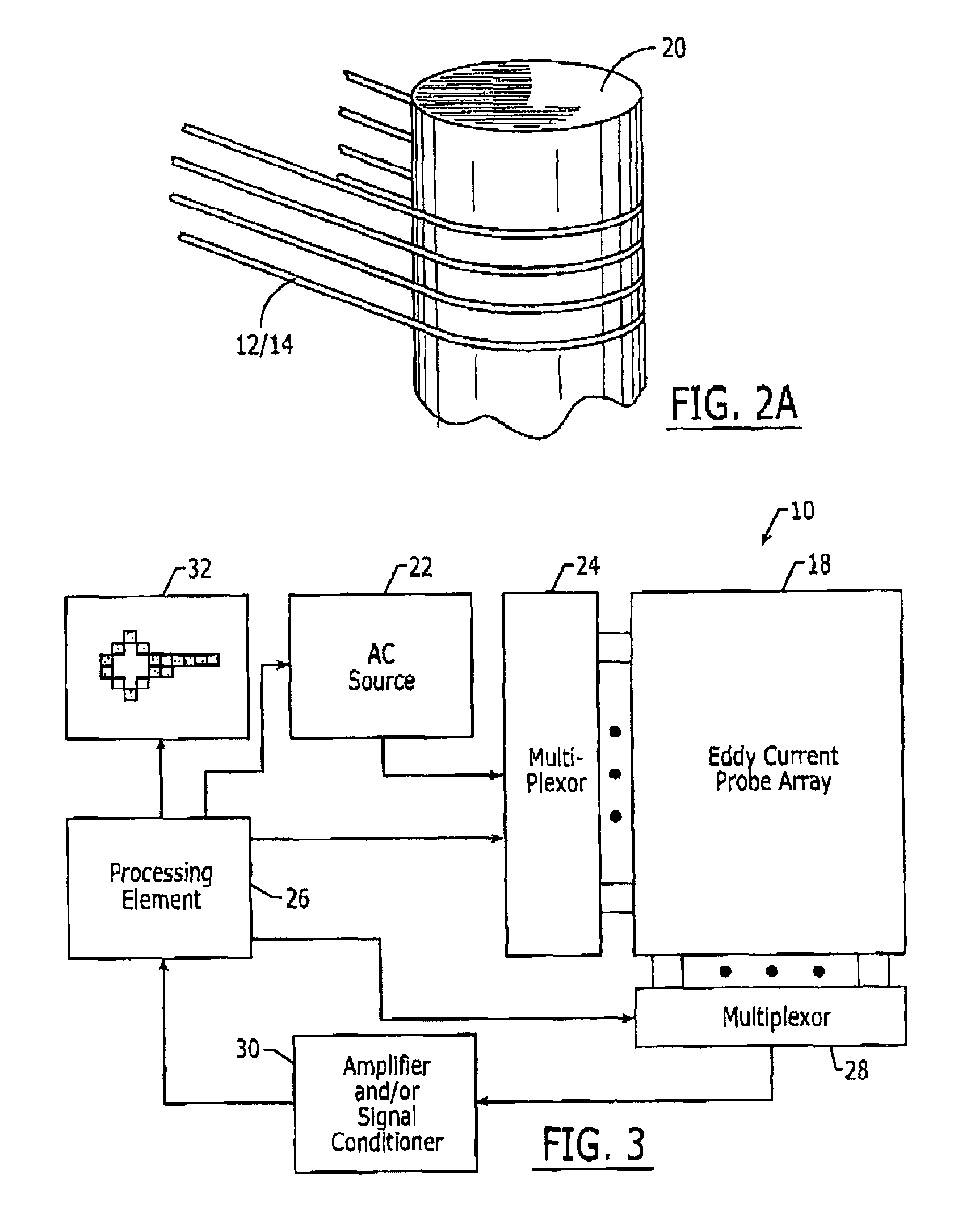
[0021]As shown by way of example in FIG. 1, an eddy current probe 10 is provided according to the present invention for conducting eddy current inspections of various objects. While FIG. 1 depicts the inspection of a portion of the surface of an aircraft, the eddy current probe and the associated inspection method of the present invention may be utilized to inspect a wide variety of other objects including other types of vehicles, bridges, buildings and other structures that are at least partially electrically ...


PUM


Abstract

An eddy current probe and associated method of inspecting a structure are provided that are capable of generating a two-dimensional image of the structure, generally in real time. The eddy current probe includes an eddy current probe array having a plurality of first and second coils that cross one another to define a plurality of sensing elements. The eddy current probe array may also include a plurality of magnetically permeable core elements located coincident with respective sensing elements and at least partially encircled by respective first and second coils. The eddy current probe may also include an alternating current source electrically connected to the first coils and sense electronics for sensing current induced in the second coils. In operation, the current sensed in the second coils represents at least one characteristic of the structure, such as the electrical conductivity of the structure.

Description

FIELD OF THE INVENTION[0001]The present invention relates generally to eddy current probes and associated inspection methods and, more particularly, to eddy current probes having a two-dimensional array of sensing elements defined by a plurality of coils that may extend perpendicularly relative to one another.BACKGROUND OF THE INVENTION[0002]One common type of non-destructive inspection (NDI) or non-destructive test (NDT) is an eddy current inspection. During this inspection process, eddy current sensors impart and detect eddy currents within a structure, particularly in metallic and other conductive structures. The data acquired by an eddy current sensor may be processed and displayed so as to identify cracks within and / or corrosion upon the structure. While eddy current inspection is advantageous for detecting cracks, eddy current inspection may be utilized in other applications known to those skilled in the art such as dent profile mapping, lightning strike evaluation, fire damag...

Claims


Application Information

Patent Timeline
IPC IPC(8): G01N27/90
CPCG01N27/904G01N27/9026G01N27/9073
Inventor GIFFORD, CARL B.UYEHARA, CLYDE T.
Owner THE BOEING CO
Learn More