Center-electrode assembly and manufacturing method therefor, nonreciprocal circuit device and communication apparatus using the same

a technology of center-electrode and manufacturing method, which is applied in the direction of basic electric elements, waveguide type devices, electrical apparatus, etc., can solve the problems of low mass production, and achieve the effect of stable electrical characteristics, convenient mass production, and easy handling

Inactive Publication Date: 2005-07-05
MURATA MFG CO LTD
View PDF12 Cites 21 Cited by
  • Summary
  • Abstract
  • Description
  • Claims
  • Application Information

AI Technical Summary

Benefits of technology

[0009]Accordingly, the present invention provides a center-electrode assembly and a manufacturing method therefor, in which electrical characteristics are stable and handling is easy, and which is suitable for mass production. The invention further provides a nonreciprocal circuit device and a communication apparatus using the center-electrode assembly.
[0011]By this structure, because the center-electrode patterns formed on the top surface of the ferrite and the conductive pattern formed on the back surface of the ferrite are electrically connected together via the connecting electrodes formed on the margins of the ferrite, the ferrite does not need to be wrapped with plate-like center-electrodes. Then, the forming of the center-electrode patterns can be carried out independently of the forming of the connecting electrodes. Thereby, accuracy of arrangement positions of the center-electrode patterns is increased so that the mutual intersecting angles of the center-electrode patterns can be kept constant.
[0012]A nonreciprocal circuit device and a communication apparatus according to the present invention comprise a center-electrode assembly having features described above so that excellent electrical characteristics are obtained.

Problems solved by technology

As a result, the mutual-intersecting angle of the center-electrodes is not stable, which may result in the center-electrodes 240 in different units having different electrical characteristics.
Also, another problems is that the operation of wrapping the ferrite 270 with the plate-like center-electrodes is troublesome and the mass-productivity is low.

Method used


Image

  • Center-electrode assembly and manufacturing method therefor, nonreciprocal circuit device and communication apparatus using the same
  • Center-electrode assembly and manufacturing method therefor, nonreciprocal circuit device and communication apparatus using the same
  • Center-electrode assembly and manufacturing method therefor, nonreciprocal circuit device and communication apparatus using the same

Examples


first embodiment

[First Embodiment, FIGS. 1 to 6]

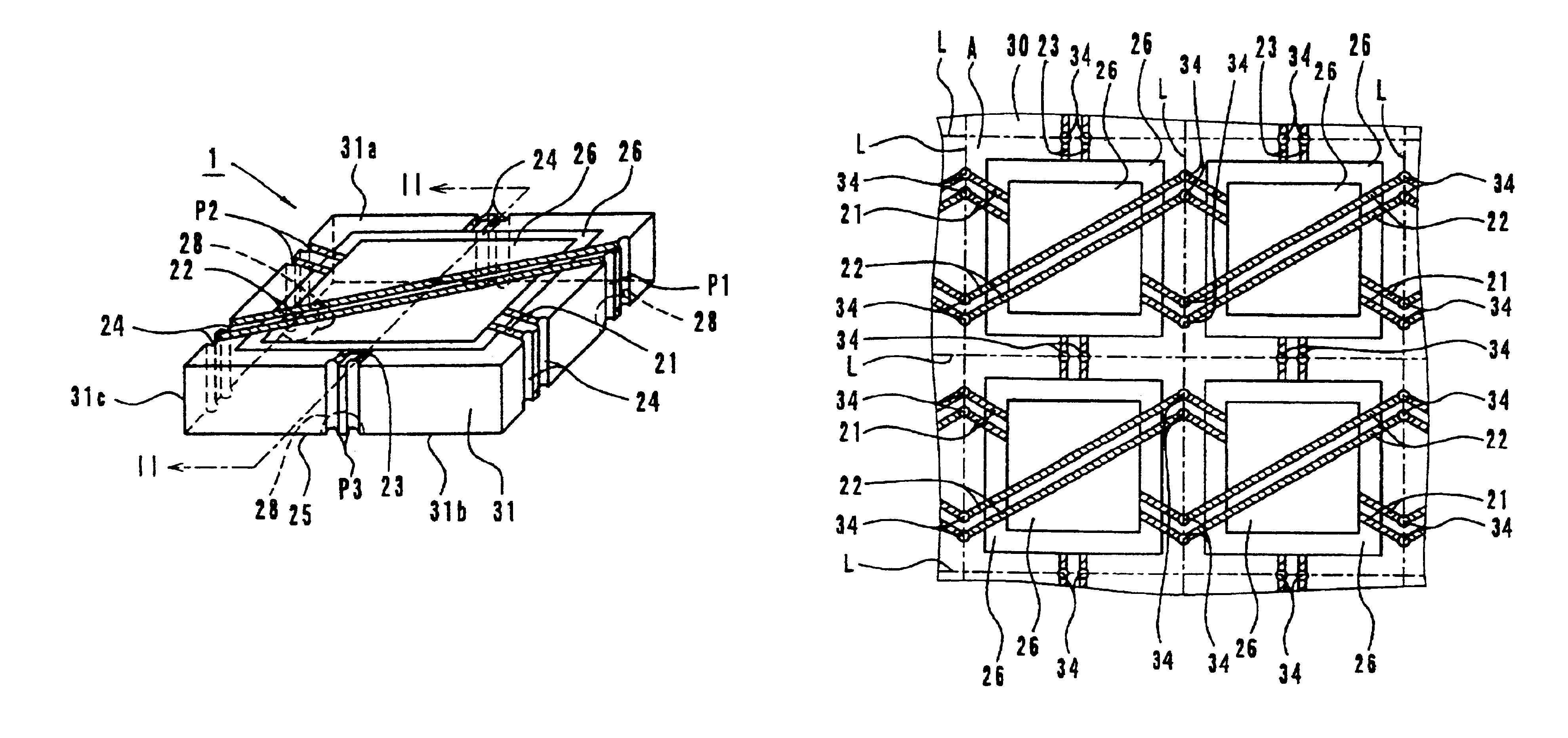
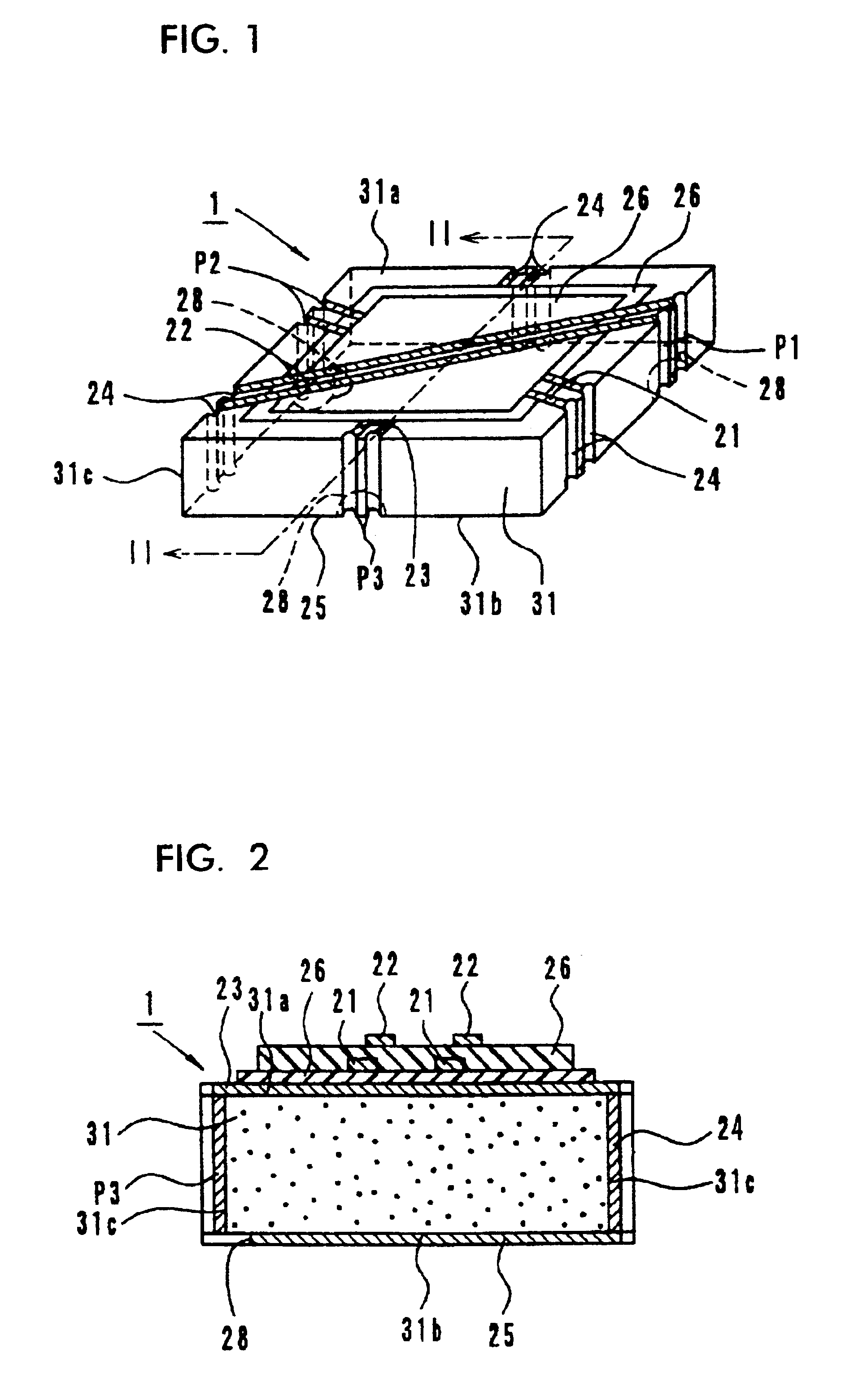
[0031]FIG. 1 is an external perspective view of an embodiment of a center-electrode assembly 1 according to the present invention, and FIG. 2 is a longitudinal sectional view of FIG. 1. A center-electrode assembly 1 comprises a block-like microwave ferrite 31, center-electrode patterns 21, 22 and 23, connecting electrodes 24, a ground pattern 25.

[0032]On the top surface (one magnetic-pole surface) 31a of the ferrite 31, three pairs of center-electrode patterns 21, 22 and 23 are arranged and intersect with each other at an angle of approximately 120° with an insulating film 26 interposed therebetween. Each pair of center-electrode patterns 21, 22, and 23 are arranged in parallel with each other. One end of each pair of center-electrode patterns 21, 22 and 23 is electrically connected to connecting electrodes 24 formed on the side-face 31c of the ferrite 31, respectively. The other end of each pair of center-electrode patterns 21, 22 and 23 is electrica...

second embodiment

[Second Embodiment, FIGS. 7 to 9]

[0041]FIG. 7 is an assembly view of an embodiment of a nonreciprocal circuit device according to the present invention and FIG. 8 is an external perspective view of the nonreciprocal circuit device 2 shown in FIG. 7 after completion of the assembling. The nonreciprocal circuit device 2 is a concentrated-constant-type isolator.

[0042]As is shown in FIG. 7, the concentrated-constant-type isolator 2 comprises a metallic lower case 4, a resin terminal case 3, the center-electrode assembly 1 shown in the first embodiment, a metallic upper case 8, a permanent magnet 9, an insulating spacer 10, a resistance element R, and matching-capacitor elements C1, C2 and C3.

[0043]In the center-electrode assembly 1, the ground pattern 25 formed on the bottom surface 31b of the ferrite 31 is connected to the bottom wall 4b of the metallic lower case 4 by a method such as soldering via a window portion 3a of the resin terminal case 3 so as to be grounded.

[0044]In the resi...

third embodiment

[Third Embodiment, FIG. 10]

[0051]A third embodiment will be described by exemplifying a portable telephone as a communication apparatus according to the present invention.

[0052]FIG. 10 is an electrical-circuit block diagram of an RF section of a portable telephone 120. In FIG. 10 shown are an antenna element 122, a duplexer 123, an isolator in the transmitting side 131, an amplifier in the transmitting side 132, an interstage band-pass filter in the transmitting side 133, a mixer in the transmitting side 134, an amplifier in the receiving side 135, an interstage band-pass filter in the receiving side 136, a mixer in the receiving side 137, a voltage-controlled oscillator (VCO) 138, and a local band-pass filter 139.

[0053]As the isolator in the transmitting side 131, the concentrated-constant-type isolator 2 according to the second embodiment can be used. By mounting the isolator 2 thereon, a portable telephone having excellent electrical characteristics can be achieved.

[Other Embodim...


PUM


Abstract

There are provided a center-electrode assembly and a manufacturing method therefor, in which electrical characteristics are stable and handling is easy, and which is suitable for mass-production, and a nonreciprocal circuit device and a communication apparatus using the center-electrode assembly. A center-electrode assembly for an isolator includes a ferrite, center-electrode patterns and insulating films deposited on the top surface of the ferrite, a ground pattern formed on the back surface of the ferrite, and connecting electrodes formed on side-faces of the ferrite. Each connecting electrode electrically connects between the center-electrode patterns formed on the top surface and the ground pattern formed on the back surface.

Description

BACKGROUND OF THE INVENTION[0001]1. Field of the Invention[0002]The present invention relates to a center-electrode assembly and a manufacturing method therefor, a nonreciprocal circuit device and a communication apparatus using the center-electrode assembly.[0003]2. Description of the Related Art[0004]A concentrated-constant-type isolator adapted for use in mobile radio communication apparatuses such as portable telephones generally has the capability of allowing a signal to pass-through in a transmission direction and of obstructing the transmission in the reverse direction.[0005]As such a concentrated-constant-type isolator, an isolator having a structure shown in FIG. 14 is known. The concentrated-constant-type isolator 200 comprises a metallic upper case 250 made from a magnetic metal, a permanent magnet 260, a center-electrode assembly 240, a terminal case 230, a metallic lower case 220 made from a magnetic metal, a spacer 280, a resistance element R, and matching-capacitor el...

Claims


Application Information

Patent Timeline
Patent Type & Authority Patents(United States)
IPC IPC(8): H01P1/32H01P1/36H01P1/383H01P11/00
CPCH01P1/36
Inventor TANAKA, YASUHIRO
Owner MURATA MFG CO LTD
Why Eureka
Try Eureka