
Imaging optical system

an optical system and optical system technology, applied in the field of optical systems, can solve the problems of unsatisfactory light collection efficiency, limited na (numerical aperture), and increase the aperture, so as to achieve the effect of reducing the number of apertures, and increasing the apertur

Inactive Publication Date: 2005-07-05
FUJIFILM HLDG CORP +1
View PDF11 Cites 12 Cited by
  • Summary
  • Abstract
  • Description
  • Claims
  • Application Information

AI Technical Summary

Benefits of technology

The present invention provides an imaging optical system that can increase the light collecting efficiency without deteriorating the resolution in the main scanning direction. This is achieved by using an erecting unit optical system consisting of a plurality of refractive index profile type optical elements, each with a refractive index profile where the refractive index is reduced towards one end in the main scanning direction. A condenser optical system with power only in the sub-scanning direction is disposed between the refractive index profile type optical elements. A light-shielding structure is provided between the refractive index profile type optical elements to improve the light collecting efficiency without deteriorating the resolution in the main scanning direction. The difference between the maximum refractive index and the minimum refractive index is not smaller than 0.02 and not larger than 0.2. The numerical aperture of the lenses can be larger and the refractive index gradient can be sharper as compared with conventional imaging optical systems, resulting in improved light collecting efficiency and resolution. The refractive index profile type optical elements can be easily produced by bonding together two axial lenses each with a refractive index profile where the refractive index is reduced towards one end in the main scanning direction.

Problems solved by technology

However, such a refractive index profile type lens array comprising a plurality of cylindrical lenses cannot be sufficiently large in refractive index profile (the difference between the maximum refractive index and the minimum refractive index) in the radial direction and is difficult to increase the aperture, which results in a limited NA (numerical aperture) and unsatisfactory light collecting efficiency.
Even if the refractive index profile can be increased, there arises a problem that the resolution in the main scanning direction in which the image is formed in an erected state at a unit magnification deteriorates when the NA is enlarged to preferentially increase the light collecting efficiency since the refractive index profile increases at the same rate in both the main scanning direction and the sub-scanning direction.

Method used


Image

  • Imaging optical system
  • Imaging optical system
  • Imaging optical system

Examples


Embodiment Construction

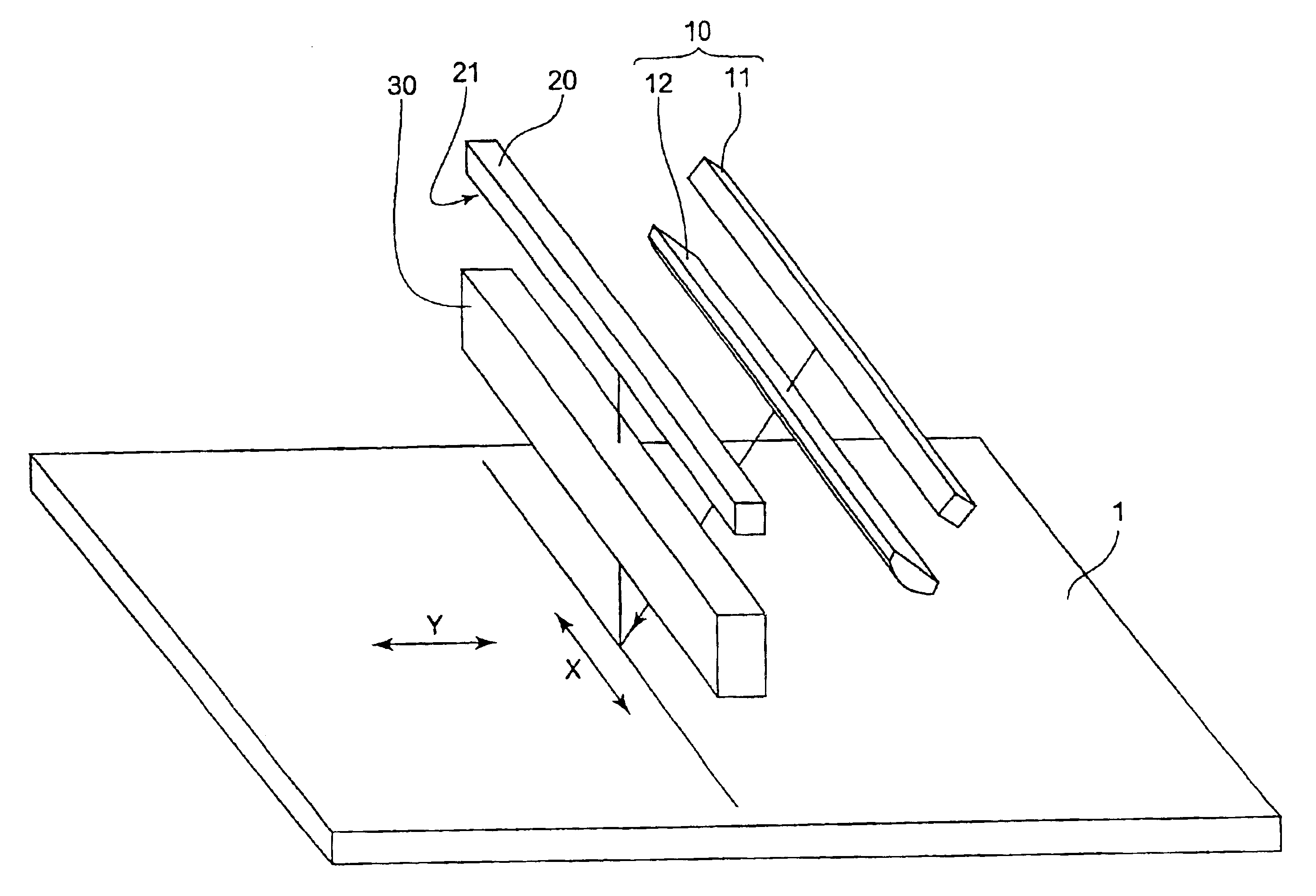
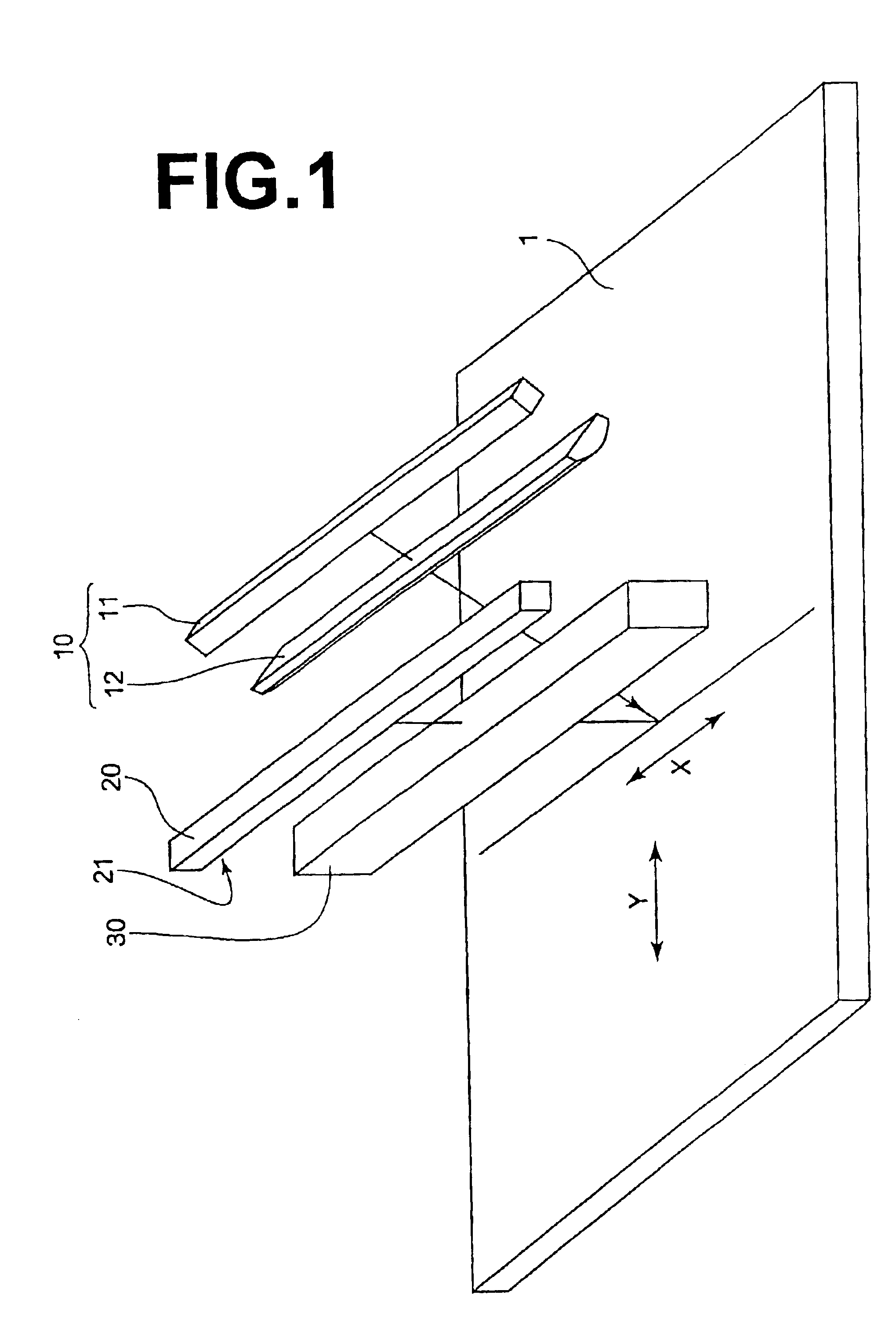
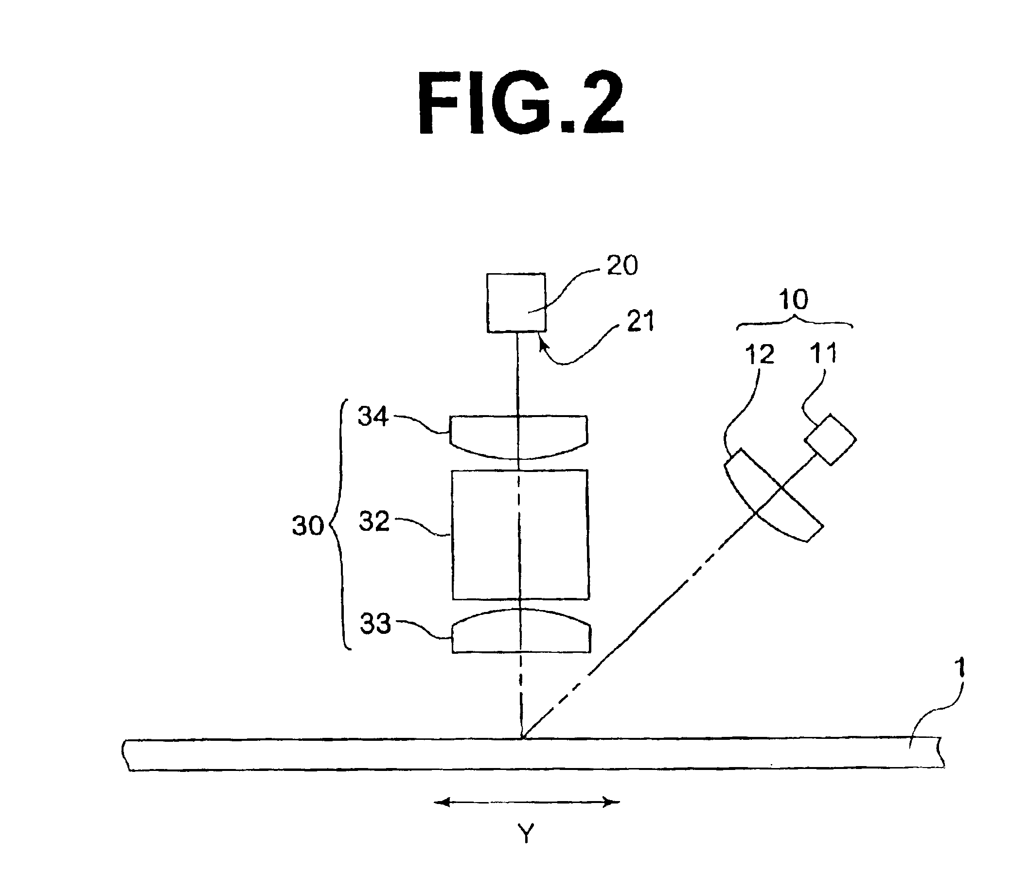
[0043]In FIGS. 1 and 2, a radiation image read-out apparatus using an imaging optical system in accordance with an embodiment of the present invention comprises a stimulating light projecting means 10 which projects, onto a stimulable phosphor sheet 1, a line-like stimulating light beam extending in the direction of arrow X (main scanning direction) while conveying the stimulable phosphor sheet 1 in the direction of arrow Y (sub-scanning direction) perpendicular to the main scanning direction, a line sensor 20 comprising a plurality of photoelectric convertor elements arranged in the main scanning direction to receive linear stimulated emission emitted from the stimulable phosphor sheet 1 upon exposure to the stimulating light beam, and an imaging optical system 30 which is disposed between the stimulable phosphor sheet 1 and the line sensor 20 to image the linear stimulated emission emitted from the stimulable phosphor sheet 1 on the light receiving face 21 of the line sensor 20.

[0...


PUM


Abstract

An imaging optical system which images a line image extending in a main scanning direction in a two-dimensional image as an erected image at a unit magnification in the main scanning direction includes an erecting unit optical system consisting of a plurality of refractive index profile type optical elements, each having a refractive index profile where the refractive index is reduced toward opposite ends in the main scanning direction from the center thereof, arranged in the main scanning direction, and a condenser optical system which is disposed along the main scanning direction on the light incident side or on the light incident side and the imaging side of the erecting unit optical system and has a power only in a sub-scanning direction. The numerical aperture in the main scanning direction the optical elements is smaller than the numerical aperture in the sub-scanning direction of the condenser optical system.

Description

BACKGROUND OF THE INVENTION[0001]1. Field of the Invention[0002]This invention relates to an imaging optical system which images a line image extending in a main scanning direction in a two-dimensional image as an erected image at a unit magnification in the main scanning direction.[0003]2. Description of the Related Art[0004]When certain kinds of phosphor are exposed to a radiation, they store a part of energy of the radiation. Then when the phosphor which has been exposed to the radiation is exposed to stimulating rays such as visible light or a laser beam, light is emitted from the phosphor in proportion to the stored energy of the radiation. A phosphor exhibiting such properties is generally referred to as “a stimulable phosphor”. In this specification, the light emitted from the stimulable phosphor upon stimulation thereof will be referred to as “stimulated emission”. There has been put into practice as CR (Computed Radiography) a radiation image recording / reproducing system in...

Claims


Application Information

Patent Timeline
Patent Type & Authority Patents(United States)
IPC IPC(8): G02B13/24G02B13/26G02B3/00G03B42/02G02B3/06G02B13/18H04N1/028H04N1/04H04N1/19H04N1/193
CPCG02B13/26H04N1/193
Inventor KARASAWA, HIROYUKI
Owner FUJIFILM HLDG CORP
Learn More