Magnetic recording disk drive with continuous contact air-bearing slider

a technology of magnetic recording disk and slider, which is applied in the direction of maintaining head carrier alignment, instruments, horology, etc., can solve the problems of inacceptable disk, and achieve the effect of minimizing the repulsive reacting force and minimizing friction and wear of slider contact pads

Inactive Publication Date: 2005-07-05
WESTERN DIGITAL TECH INC
View PDF16 Cites 13 Cited by
  • Summary
  • Abstract
  • Description
  • Claims
  • Application Information

AI Technical Summary

Benefits of technology

[0005]The invention is based in part on the discovery that in a continuous contact recording slider-disk interface there is a significant adhesive force between the slider and disk that must be considered to successfully achieve continuous contact recording. The invention is a magnetic recording disk drive with a head-suspension assembly that provides continuous contact recording yet compensates for the moment generated from the adhesive force between the slider and the disk by generating a counteracting moment about the slider pivot point, which is the point where the load force is applied to the flexure that supports the slider. The pivot point is located closer to the front end of the slider than the net force applied by the air-bearing surface of the slider when the disk is rotating at its operational speed. This assures that the net air-bearing force generates a moment about the pivot point to partially counteract the flexure moment and the moment generated from the adhesive force between the disk and the slider's contact pad

Problems solved by technology

Thus attempts at continuous contact recording have resulted in unacceptab

Method used


Image

  • Magnetic recording disk drive with continuous contact air-bearing slider
  • Magnetic recording disk drive with continuous contact air-bearing slider
  • Magnetic recording disk drive with continuous contact air-bearing slider

Examples


first embodiment

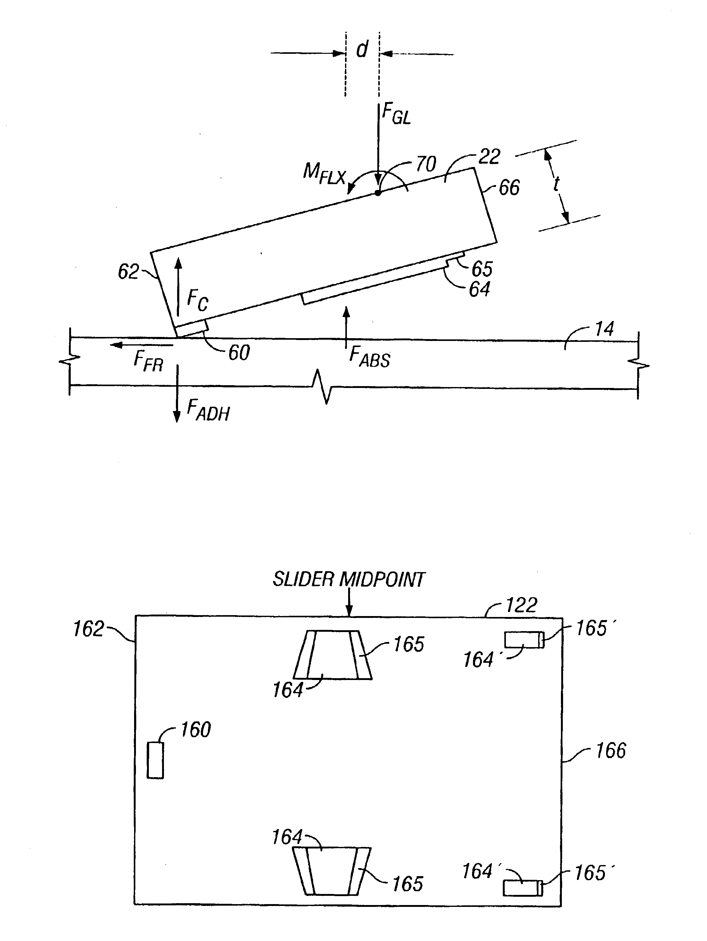
[0022]FIG. 6 illustrates the present invention wherein the pivot point 70 is located other than at the midpoint on the slider top side, preferably at a point between the midpoint and the slider front end 66. The locating of the pivot point more forward can be accompanied by a design of the ABS (flying pads 64) that moves the FABS more rearward.

second embodiment

[0023]Because the slider midpoint is the pivot location for conventional head-suspension assemblies, locating the pivot point other than at the slider midpoint could cause major redesign of conventional commercially available suspensions and new development of the conductor leads and wire termination process required for electrical connection to the read / write head located on the slider trailing end 62. For this reason the present invention is a center-pivot head-suspension assembly with an ABS design, as shown in FIG. 7, that locates the FABS between the slider midpoint and the trailing end 162 of the slider 122. The disk side of the slider 122 for this embodiment is shown in FIG. 7, wherein smaller flying pads 164′ (with step edges 165′) are located near the front end 166 and larger flying pads 164 (with step edges 165) are located near the slider midpoint with the major portion of the total ABS area being located between the slider midpoint and the slider trailing end 162. Becaus...


PUM


Abstract

A magnetic recording disk drive achieves continuous contact recording with a head-suspension assembly that compensates for the moment generated from an adhesive force between the head carrier or slider and the disk. The slider pivot point, which is the point where the load force is applied to the flexure that supports the slider, is located closer to the front end of the slider than the net force applied by the air-bearing surface of the slider when the disk is rotating at its operational speed. This assures that the net air-bearing force generates a moment about the pivot point to partially counteract the flexure moment and the moment generated from the adhesive force between the disk and the slider's contact pad.

Description

TECHNICAL FIELD[0001]This invention relates in general to magnetic recording disk drives and in particular to a magnetic recording disk drive that uses an air-bearing slider for continuous contact recording.BACKGROUND OF THE INVENTION[0002]In conventional magnetic recording rigid disk drives, each of the read / write transducers (or heads) is supported on an air-bearing slider that rides on a cushion or bearing of air above the surface of its associated disk surface when the disk is rotating at its operating speed. The slider is connected to an actuator by means of a relatively fragile suspension. The suspension includes a gimbal or flexure that supports the slider and allows it to pitch and roll, and a load beam with a dimple or tip that applies a small force to bias the slider toward the disk surface. The slider has an air-bearing surface (ABS) designed to generate an air-bearing force to counteract the bias force from the load beam and thus assure that the slider “flies” above and ...

Claims


Application Information

Patent Timeline
IPC IPC(8): G11B5/58G11B5/48G11B17/32G11B21/21
CPCG11B5/4826G11B5/4833G11B5/58G04B19/042G04B19/065G04B19/16
Inventor ALBRECHT, THOMAS R.LEE, FRANCIS CHEE-SHUENMATE, CHARLES MATHEWPAN, TZONG-SHIIPAYNE, ROBERT N.
Owner WESTERN DIGITAL TECH INC
Why Eureka
Try Eureka