
Method of estimating floor reactions of bipedal walking body, and method of estimating joint moments of bipedal walking body

Inactive Publication Date: 2005-07-05
HONDA MOTOR CO LTD
View PDF37 Cites 29 Cited by
  • Summary
  • Abstract
  • Description
  • Claims
  • Application Information

AI Technical Summary

Benefits of technology

[0027]Therefore, according to the method of estimating a floor reaction force of the present invention, it is possible to grasp the floor reaction forces in real time by the relatively simple technique without attaching force sensors to ankle portions or foot portions of the bipedal walking moving body, or using a force place.
[0048]According to the method of estimating a moment of the present invention as described above, by estimating the moments acting on the joints of the leg bodies using the estimated values of the floor reaction forces derived by the foregoing floor reaction force estimating method of the present invention, it is possible to relatively accurately estimate in real time the moments acting on the joints of the leg bodies without attaching the relatively large sensors and so forth to the bipedal walking moving body.

Problems solved by technology

However, inasmuch as the foregoing technique aims to grasp the floor reaction forces on the leg bodies with respect to one step or a plurality of steps of the bipedal walking moving body, when a gait of the bipedal walking moving body changes in sequence, it is difficult to accurately grasp the floor reaction forces.
Therefore, it is difficult to accurately grasp the floor reaction forces with a reduced influence of environment for movement of the bipedal walking moving body or a difference in individuality of the bipedal walking moving body.
However, the technique using the force sensors has a disadvantage that when grasping floor reaction forces on leg bodies of particularly a human being, inasmuch as the force sensors should be attached to ankle portions or foot portions of the human being, the force sensors become obstructive to the walking in an ordinary living environment.
Further, in case of the one using the force plate, the floor reaction forces can only be grasped in an environment where the force plate is arranged.

Method used


Image

  • Method of estimating floor reactions of bipedal walking body, and method of estimating joint moments of bipedal walking body
  • Method of estimating floor reactions of bipedal walking body, and method of estimating joint moments of bipedal walking body
  • Method of estimating floor reactions of bipedal walking body, and method of estimating joint moments of bipedal walking body

Examples


Embodiment Construction

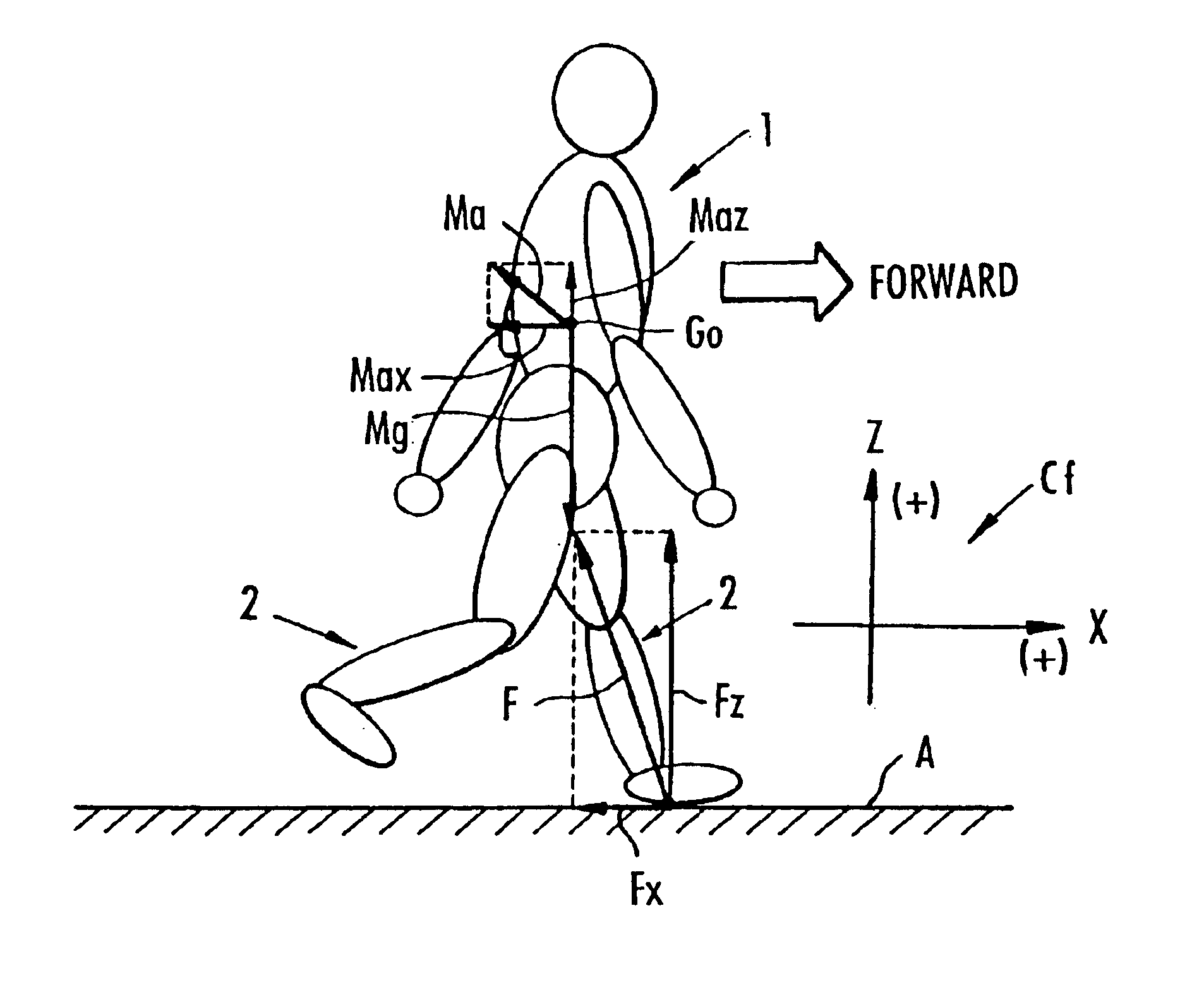
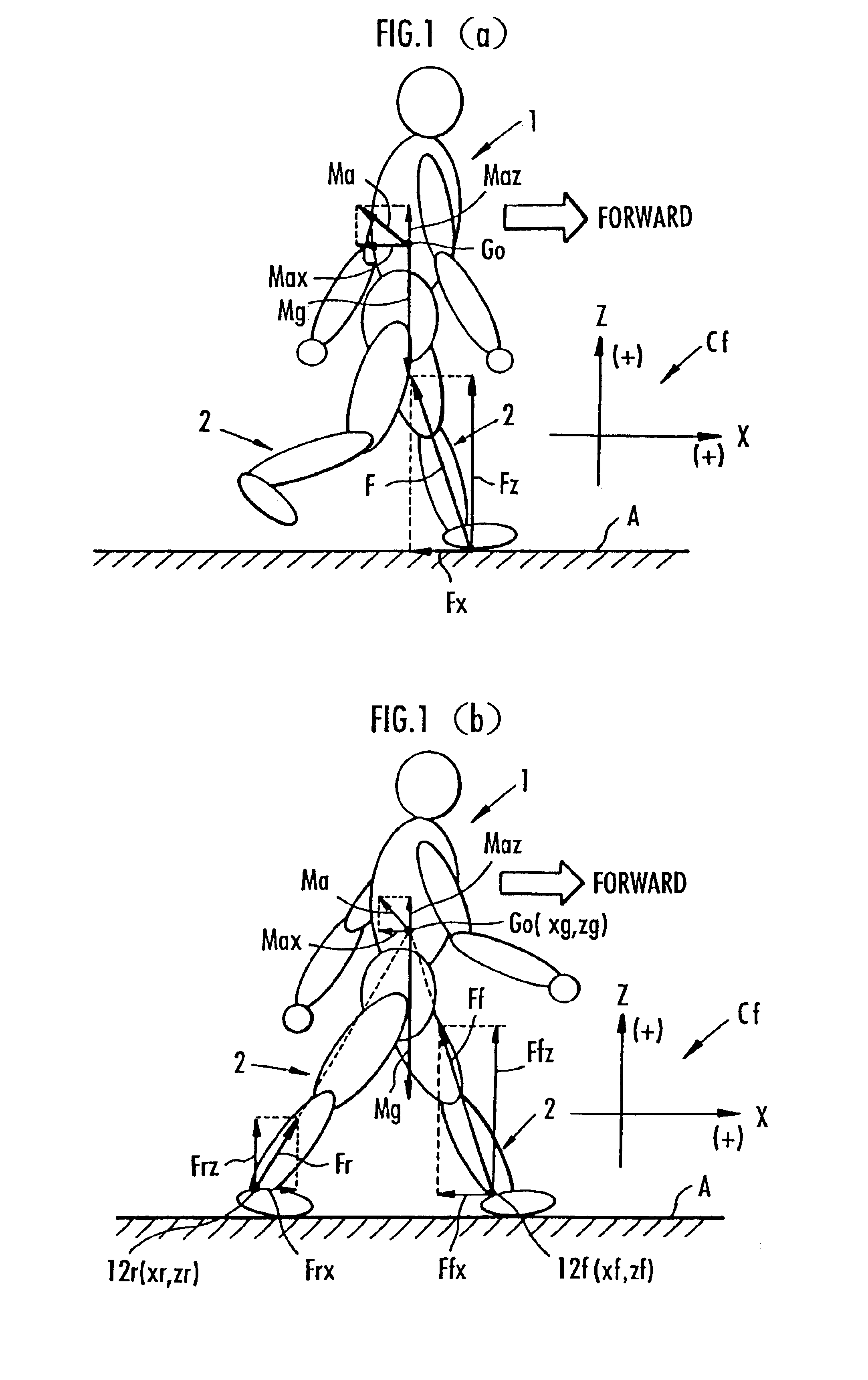
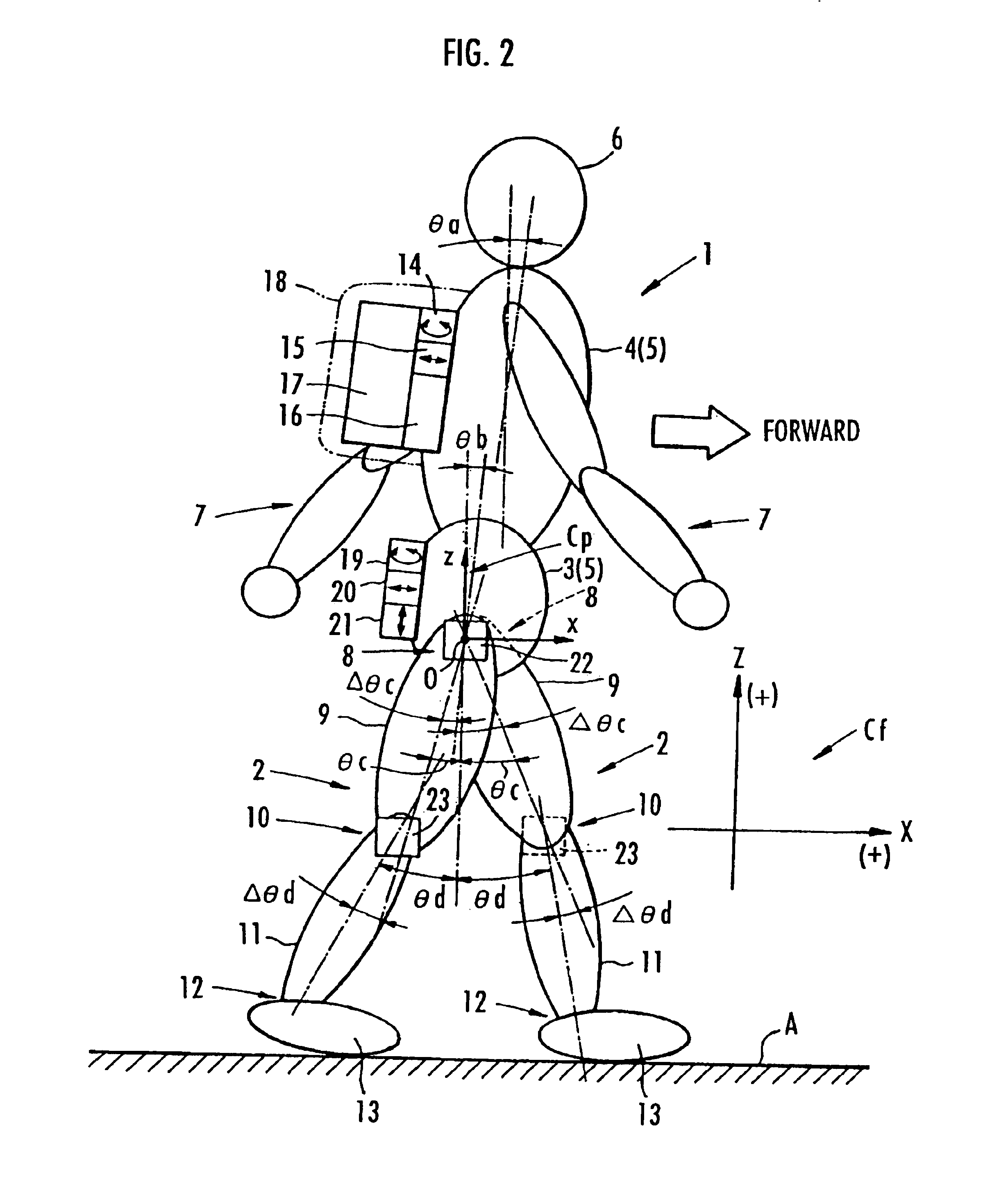
[0064]One embodiment of the present invention will be described with reference to the foregoing FIG. 1 and FIGS. 2 to 10.

[0065]The present embodiment is an embodiment wherein a floor reaction force estimating method and a method of estimating a moment of the present invention are applied to a human being as a bipedal walking moving body.

[0066]As exemplarily shown in FIG. 2, a human being 1, when its structure is roughly classified, has a pair of left and right leg bodies 2, 2, a body 5 comprising a waist 3 and a chest 4, a head 6, and a pair of left and right arm bodies 7, 7. The waist 3 is coupled to the respective leg bodies 2, 2 via a pair of left and right hip joints 8, 8 so that the body 5 is supported on both leg bodies 2, 2. Further, the chest 4 of the body 5 is disposed on an upper side of the waist 3 so as to be free inclined toward a forward side of the human being 1 relative to the waist 3. And, the arm bodies 7, 7 extend from both left and right side portions of an upper...


PUM


Abstract

A method is presented for determination of single stance or double stance state of leg bodies of a bipedal mobile body (BMB). In a single stance state, a floor reaction force acting on a leg body touching the ground is estimated based on an equation of motion for the center of gravity (GO) of a BMB. In a double stance state, floor reaction forces, Fr and Ff respectively, acting on the leg bodies are estimated based on an equation of motion for GO of a BMB and an expression of relation between components of Fr and Ff on the respective leg bodies and positions of ankle portions of the leg bodies relative to the GO of the BMB. Further, based on an inverse dynamics model, knee and hip joint moments of each leg body are estimated using floor reaction force values.

Description

TECHNICAL FIELD[0001]The present invention relates to a method of estimating floor reaction forces acting on leg bodies of a bipedal walking moving body such as a human being or a bipedal walking robot, and further relates to a method of estimating moments acting on joints of the leg bodies of the bipedal walking moving body by the use of estimated values of the floor reaction forces.BACKGROUND ART[0002]For example, when executing an operation control of a walking assist device assisting walking motions of a human being, or a control of moving motions of a bipedal walking robot, it becomes necessary to successively grasp floor reaction forces acting on leg bodies (specifically, forces acting on ground touching portions of the leg bodies from a floor) of the human being or the bipedal walking robot. By grasping the floor reaction forces, it becomes possible to grasp moments or the like acting on joints of the leg bodies of the bipedal walking moving body and, based on the grasped mom...

Claims


Application Information

Patent Timeline
IPC IPC(8): A61B5/103A61B5/024G01L1/00A61F2/72A61H3/00B25J5/00B25J9/00
CPCA61B5/1038A61B5/4528A61H3/008B25J9/0006B62D57/032A61B5/024A61B5/1116A61F2/72A61H3/00A61H2201/5061A61H2201/5069A61H2201/5079A61H2201/5084B25J5/00
Inventor KAWAI, MASAKAZUIKEUCHI, YASUSHIKATOH, HISASHI
Owner HONDA MOTOR CO LTD
Learn More