Device for estimating moving object travel direction and method for estimating travel direction

Active Publication Date: 2015-07-30
NAT INST OF ADVANCED IND SCI & TECH
View PDF1 Cites 9 Cited by
  • Summary
  • Abstract
  • Description
  • Claims
  • Application Information

AI Technical Summary

Benefits of technology

[0031]The travel direction estimating device and travel direction estimating method of the present invention each allow accurate estimation of a travel direction even in the case where changes occur in (i)

Problems solved by technology

On the other hand, in the case where the self-contained sensing device is held at a position and in a posture that freely cha

Method used


Image

  • Device for estimating moving object travel direction and method for estimating travel direction
  • Device for estimating moving object travel direction and method for estimating travel direction
  • Device for estimating moving object travel direction and method for estimating travel direction

Examples


Example

[0044]The description below deals with a first embodiment of the present invention with reference to drawings.

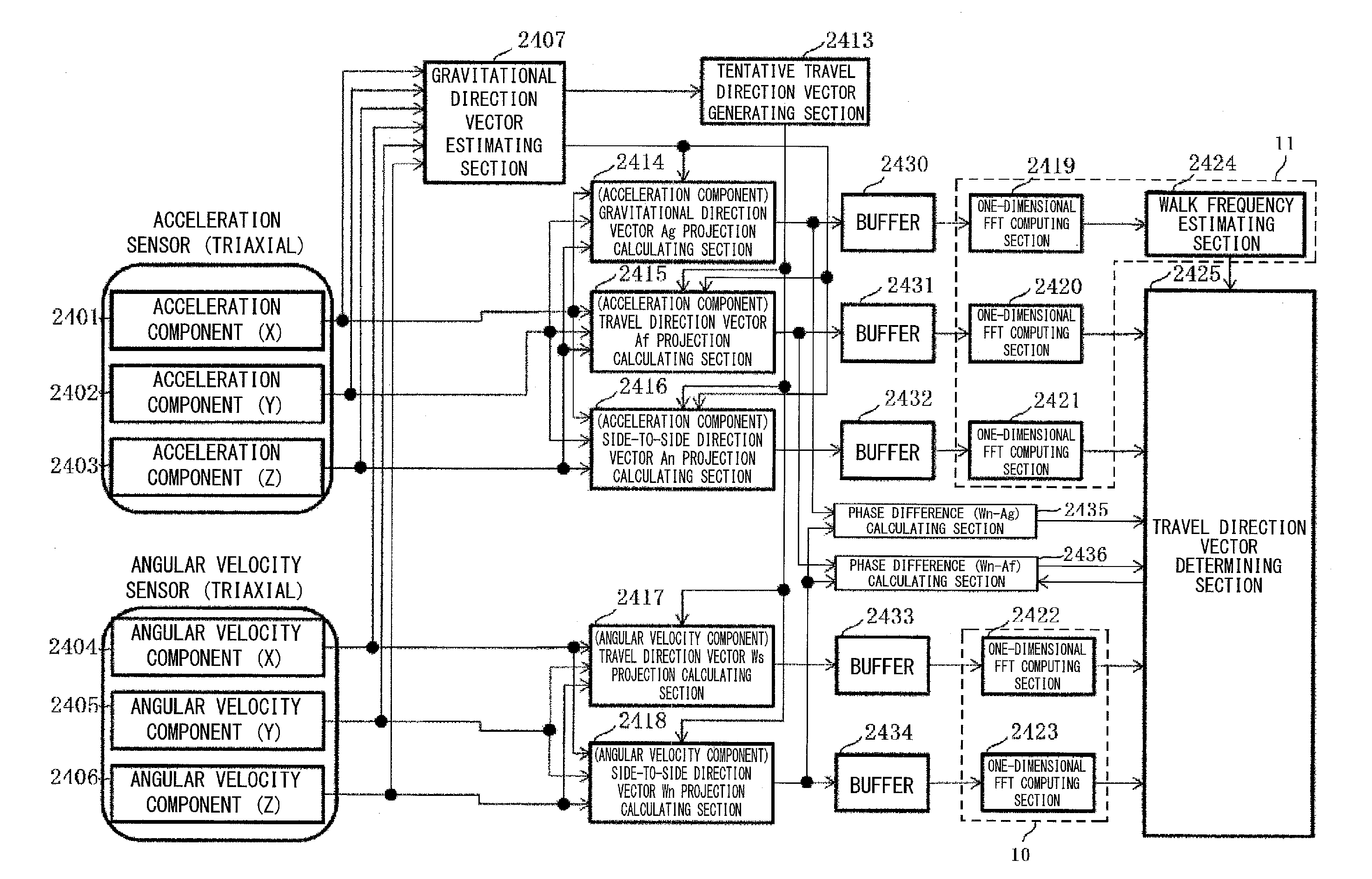
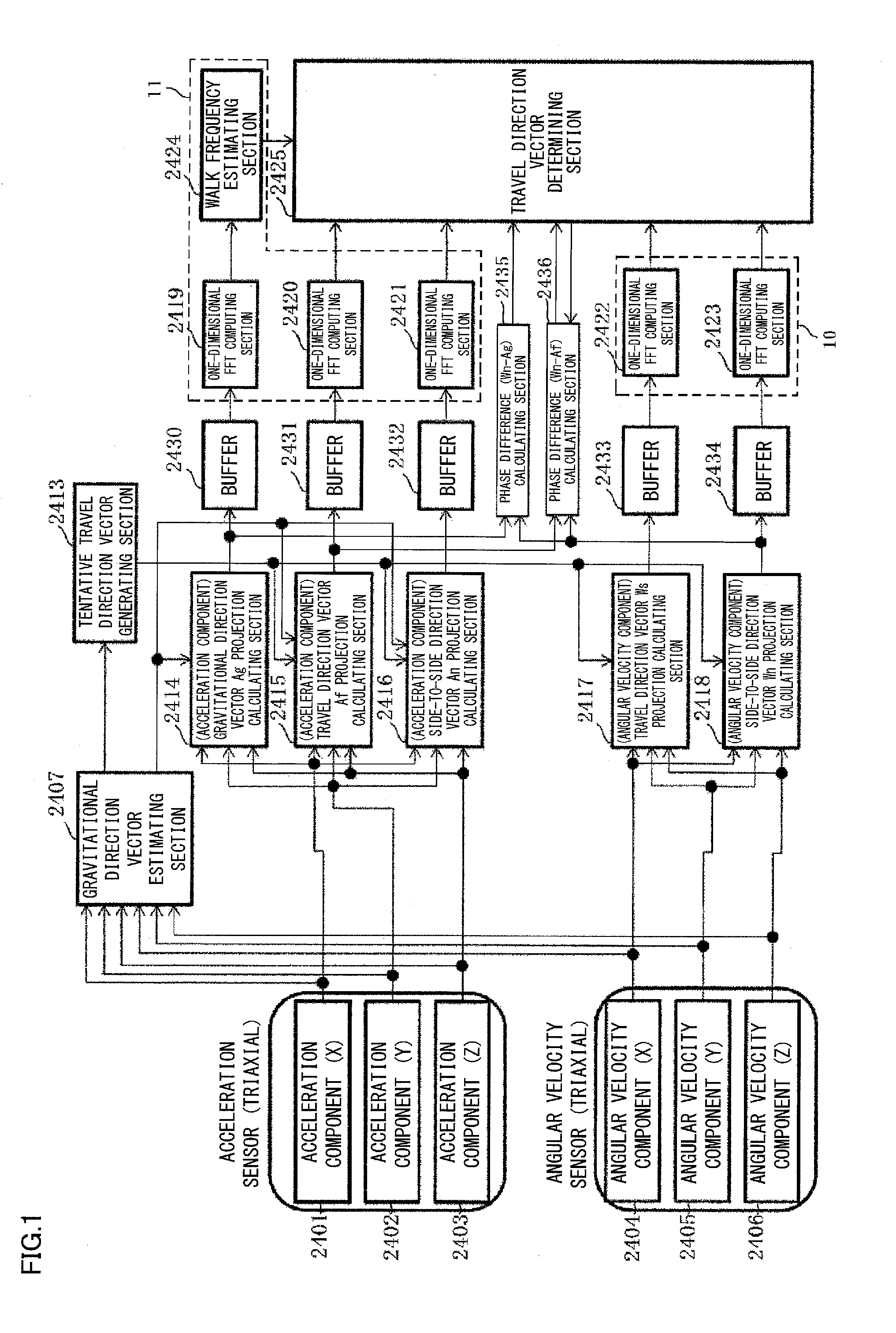
[0045]FIG. 1 is a functional block diagram illustrating a basic configuration of a device of the first embodiment of the present invention for estimating a travel direction of a moving body.

[0046]The travel direction estimating device illustrated in FIG. 1 includes, as measuring sections, an acceleration sensor (triaxial) 2401, 2402, 2403 and an angular velocity sensor (triaxial) 2404, 2405, 2406 both mounted in a terminal device, such as a smartphone or portable terminal, attached to or held by a moving body (for example, a walker). The above sensors do not necessarily produce their respective outputs on an identical coordinate system. Their outputs are, however, subjected to a coordinate transformation to be eventually transformed into coordinates that can be handled on an identical rectangular coordinate system (on X, Y, and Z axes).

[0047]The acceleration sensor includes ...

Example

Second Embodiment

[0125]The description below deals with a second embodiment of the present invention. The second embodiment of the present invention assumes that the travel direction has not changed over a predetermined period (for example, 128 samples=1.28 seconds, for 100 Hz) and thus intends to reduce the calculation cost of discrete Fourier transform. The description below of the present embodiment does not deal with any constituent member similar to a corresponding constituent member described above for the first embodiment.

[0126]FIG. 11 is a functional block diagram illustrating a basic configuration of a device of the second embodiment of the present invention for estimating a travel direction of a moving body. The travel direction estimating device includes an acceleration sensor (triaxial) 2501, 2502, 2503 and an angular velocity sensor (triaxial) 2504, 2505, 2506, which include six sensing sections on a rectangular coordinate system as measuring sections for a moving body....


PUM


Abstract

The present invention provides a device and method for estimating a travel direction of a moving body, the device and method allowing highly accurate estimation of the travel direction even in the case where the positional relationship between the moving body and the self-contained sensing device or the posture is changed freely.
The travel direction estimating device includes (i) a gravitational direction vector estimating section 2407 for estimating a gravitational direction vector on the basis of respective outputs of an acceleration sensor and an angular velocity sensor, (ii) a tentative travel direction vector generating section 2413 as a candidate of travel direction vector, (iii) a walk frequency estimating section 2424 for estimating a walk frequency from component data resulting from projecting acceleration component data for the gravitational direction vector, and (iv) a travel direction vector determining section 2425 for determining an objective function and a phase difference on the basis of a frequency component of a component Af resulting from projecting the acceleration component data for a travel direction vector, a frequency component of a component An resulting from projecting the acceleration component data for a side-to-side direction vector, a frequency component of a component Ws resulting from projecting angular velocity component data for the travel direction vector, a frequency component of a component Wn resulting from projecting the angular velocity component data for the side-to-side direction vector, a walk frequency, and the phase of the walk frequency, selecting as travel direction vectors, tentative travel direction vectors with which the phase difference is within a predetermined range and each of which maximizes the value of the objective function, and determining the side of the travel direction.

Description

TECHNICAL FIELD[0001]The present invention relates to a technique of estimating a travel direction of a moving body.BACKGROUND ART[0002]There has been a practice of estimating a move direction of a moving body on the world coordinate system on the basis of measurement data generated by a self-contained sensing device (for example, an acceleration sensor, a magnetic sensor, a gyroscope, or an atmospheric pressure sensor) built in a terminal held by the moving body (for example, a walker) (Non Patent Literature 1).[0003]Estimating a move direction of a moving body on the world coordinate system requires estimating the following three vectors simultaneously on a sensor coordinate system of the self-contained sensing device: (1) a gravitational direction vector, (2) a horizontal reference direction vector (for example, the direction of true north), and (3) a travel direction vector.[0004]Estimating (tracking) the above vectors (1) to (3) allows estimation of the angle formed by the trav...

Claims


Application Information

Patent Timeline
IPC IPC(8): G01C21/10G01P15/00G01P3/00
CPCG01C21/10G01P15/00G01P3/00G01P13/02G01C21/16G01C22/006
Inventor KOUROGI, MASAKATSUKURATA, TAKESHIISHIKAWA, TOMOYAOKUMA, TAKASHI
Owner NAT INST OF ADVANCED IND SCI & TECH
Why Eureka
Try Eureka