
Heating process apparatus

Active Publication Date: 2010-05-06
CANON ANELVA CORP
View PDF7 Cites 8 Cited by
  • Summary
  • Abstract
  • Description
  • Claims
  • Application Information

AI Technical Summary

Benefits of technology

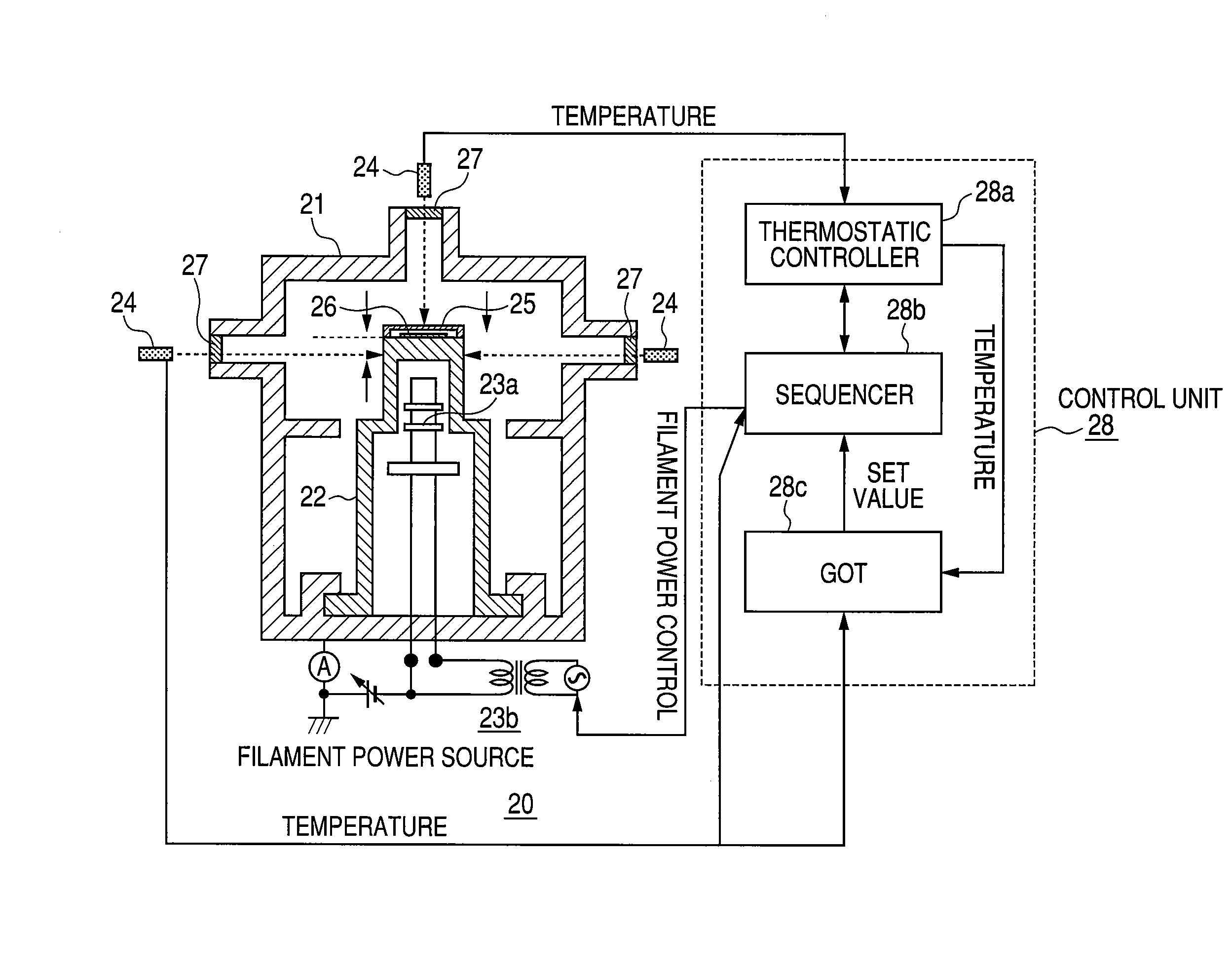
[0010]A heating process apparatus 20 according to the present invention measures temperature based on the ratio between intensities of two wavelengths in an infrared radiation region. Therefore, the temperature of the cap 25 or the heat-processed object support member 22 can be directly measured in a noncontact manner under constantly stable conditions without being affected by the conditions of the surface of the heat-processed object support member 22 and the heat receiving element (cap) 25 and the temperature of a substrate 26 can be accurately estimated. In addition, the use of the temperature measuring means 24 enables reliable measurement of temperatures in a high-temperature range higher than 1850 degrees (for example, 2400 degrees), in which temperature control was unable to be accomplished with a tungsten-rhenium (W-Re) thermo couple.
[0011]Furthermore, the use of the heating process apparatus 20 according to the present invention can prevent displacement of a substrate 26 which would otherwise occur during evacuation of the heating process chamber 21, to enable measurement of emitted light under constant conditions, thereby high reliability can be achieved.
[0012]Moreover, by using the heating process apparatus 20 according to the present invention20, the heat capacity can be kept constant independently of the size of each individual substrate 26 and therefore the temperature of the substrates can be reproductively controlled with respect to heating power. In addition, temperature variations depending on substrate size corresponding to one set temperature are eliminated and substrate temperature check is enabled. Because the heat capacity is kept constant, variations in emission current value are eliminated and a reproducible start of temperature rise can be achieved in the temperature rising process.

Problems solved by technology

In addition, temperature control in a high-temperature range higher than 1850 degrees, which is the biggest issue, can be accomplished.

Method used


Image

  • Heating process apparatus
  • Heating process apparatus
  • Heating process apparatus

Examples


Embodiment Construction

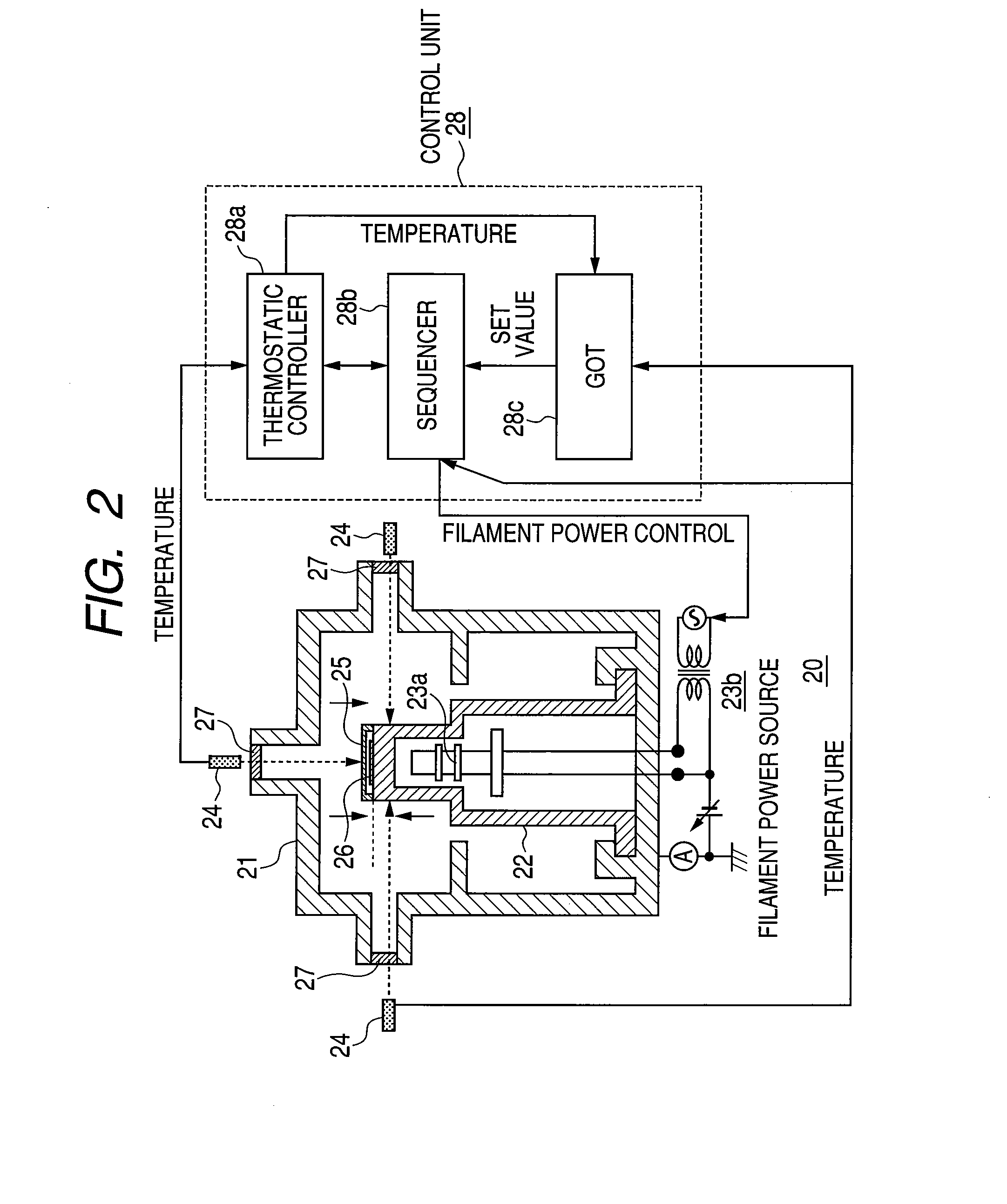
[0083]A first exemplary embodiment of the present invention will be described with reference to FIGS. 2 to 6. FIG. 2 schematically shows a heating process apparatus. A heat-processed object support member 22 is placed in an evacuatable heating process chamber 21 (vacuum vessel). The interior of the heat-processed object support member 22 is also structured to be evacuatable. A heater 23 which includes a filament 23a capable of heating the upper portion of the heat-processed object support member 22 and a filament power supply 23b is contained within the heat-processed object support member 22. In the present embodiment, a temperature measuring means 24 capable of measuring the temperatures of the upper and side surfaces of the heat-processed object support member 22 is provided on the outer side of the peripheral wall of the heating process chamber 21 so that the temperatures of a cap 25 and the heat-processed object support member 22 can be measured at the same time. The temperatur...


PUM


Abstract

An object of the present invention is to provide a heating process apparatus capable of being controlled to a constant temperature and to temperatures in a high-temperature range higher than or equal to a 1850 degrees. A heating process apparatus includes: a process chamber; a heat-processed object support member provided in the process chamber; a heater provided inside the heat-processed object support member; and temperature measuring means for measuring the temperature of the heat-processed object support member; wherein the temperature measuring means is provided outside a transmissive window provided in a peripheral wall of the process chamber and through which infrared energy radiated from the heat-processed object support member can be transmitted; and the temperature measuring means comprises a collector collecting infrared energy radiated from the heat-processed object support member and a calculating unit calculating temperature based on the ratio between the intensities of two wavelengths in the infrared.

Description

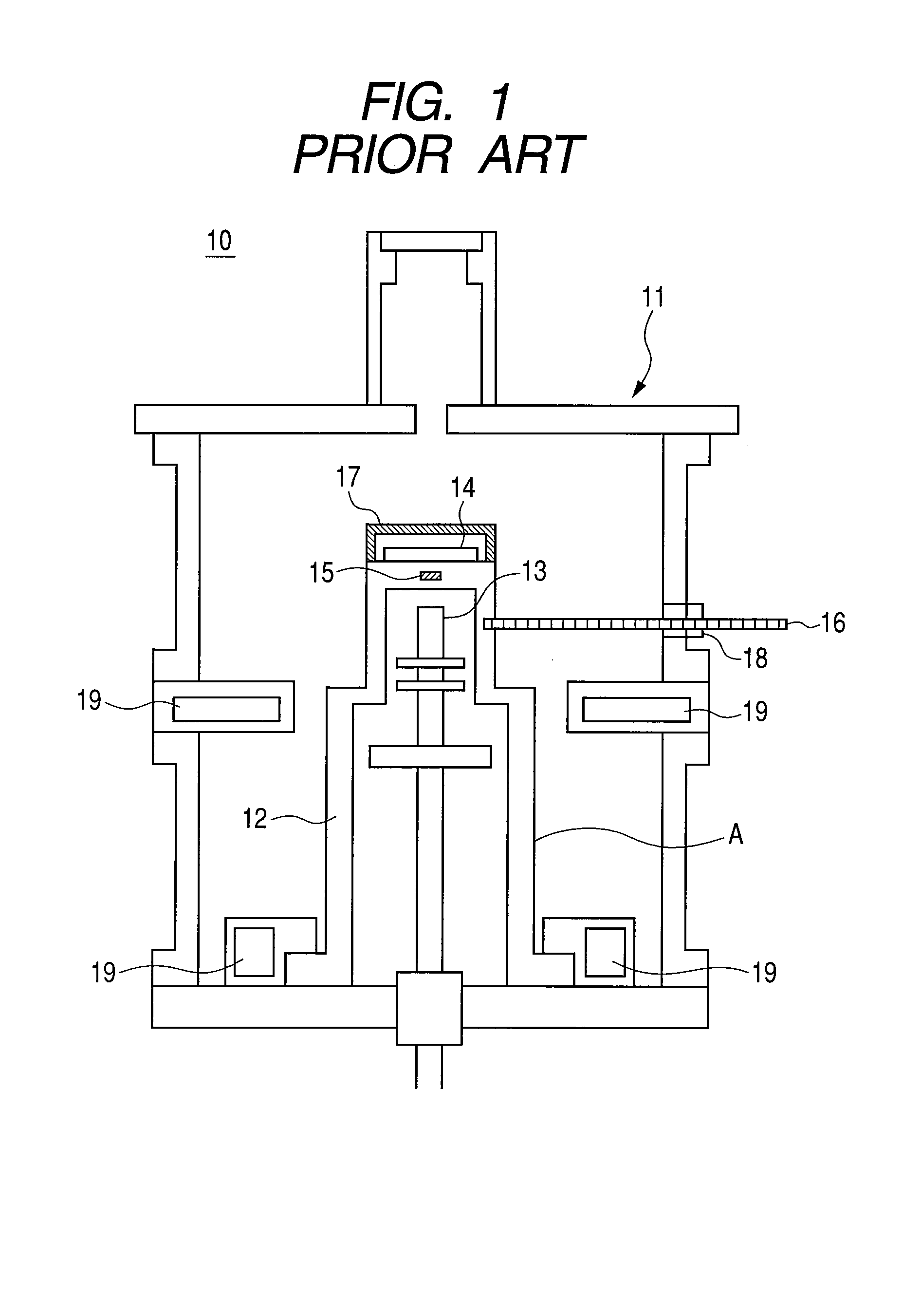
CROSS-REFERENCES TO RELATED APPLICATIONS[0001]This application is a continuation application of International Application No. PCT / JP2007 / 060021, filed on May 16, 2007, the entire contents of which are incorporated by reference herein.TECHNICAL FIELD[0002]The present invention relates to a heating process apparatus.BACKGROUND ART[0003]FIG. 1 is a cross-sectional view of a conventional heating process apparatus 10. A heating process chamber 11 is a chamber made of water-cooled aluminum with a reflectance improved by mirror finishing of its inner wall and has a fluid flowing section 19 in which a cooling fluid can flow. The heating process chamber 11 can be evacuated to a vacuum of approximately 10−2 Pa. However, a heating process can also be performed at atmospheric pressure.[0004]A heater 13 including a filament and a filament power supply is contained inside a heat-processed object support member (susceptor) 12 coated with a coating layer A of pyrolytic carbon. A substrate 14 to be ...

Claims


Application Information

Patent Timeline
IPC IPC(8): F27B5/06
CPCG01J5/60G01J5/62G01J5/0805
Inventor KUMAGAI, AKIRASHIBAGAKI, MASAMINUMAJIRI, KENJIEGAMI, AKIHIRO
Owner CANON ANELVA CORP
Learn More