
Control device of internal combustion engine

Active Publication Date: 2009-10-29
DENSO CORP
View PDF7 Cites 10 Cited by
  • Summary
  • Abstract
  • Description
  • Claims
  • Application Information

AI Technical Summary

Benefits of technology

[0028]The air excess ratio equivalent value can be estimated accurately with the above methods. Moreover, the target value of the ignition timing and the ignition delay at the air excess ratio equivalent value can be calculated appropriately by using the accurate estimate of the air excess ratio equivalent value. Accordingly, the contro

Problems solved by technology

Also in the case of the lean combustion as the basic combustion, there is a possibility that the air-fuel ratio deviates from the target to the rich side when intake system control cannot be performed suitably during acceleration or the like, for example.
If the ignition timing deviates largely from the adjusted state to the advanced side of the optimum ignition timing, the combustion progresses excessively, thereby causing problems such as a noise and excessive torque, for example.
If the ignition timing deviates largely to the delayed side of the optimum ignition timing, for example, problems such as a misfire, increase of unburned fuel in the exhaust gas or insufficient torque can occur.
It is known that the rich combustion has a high tendency to cause incomplete combustion, thereby increasing emission of soot from the engine.
However, in the example of the conventional technology shown in FIG. 6, the actual ignition timing shown by a solid line in part (e) is not delayed fully to the target value shown by a broken line in part (e).
It is regarded that the problem shown in FIG. 6 is caused because the command value of the injection timing in the transient state is not calculated appropriately.
If it is not taken into account that the ignition delay also differs because of the difference in the ignition timing, suitable injection timing cannot be obtained.
Moreover, the ignition delay is affected by existence / nonexistence of pilot injection, injection quantity of the pilot injection and injection timing of the pilot injection.
Therefore, unless such the increase / decrease in the ignition delay is taken into account, suitable injection timing cannot be calculated in the state where the in-cylinder oxygen quantity changes suddenly.

Method used


Image

  • Control device of internal combustion engine
  • Control device of internal combustion engine
  • Control device of internal combustion engine

Examples


Embodiment Construction

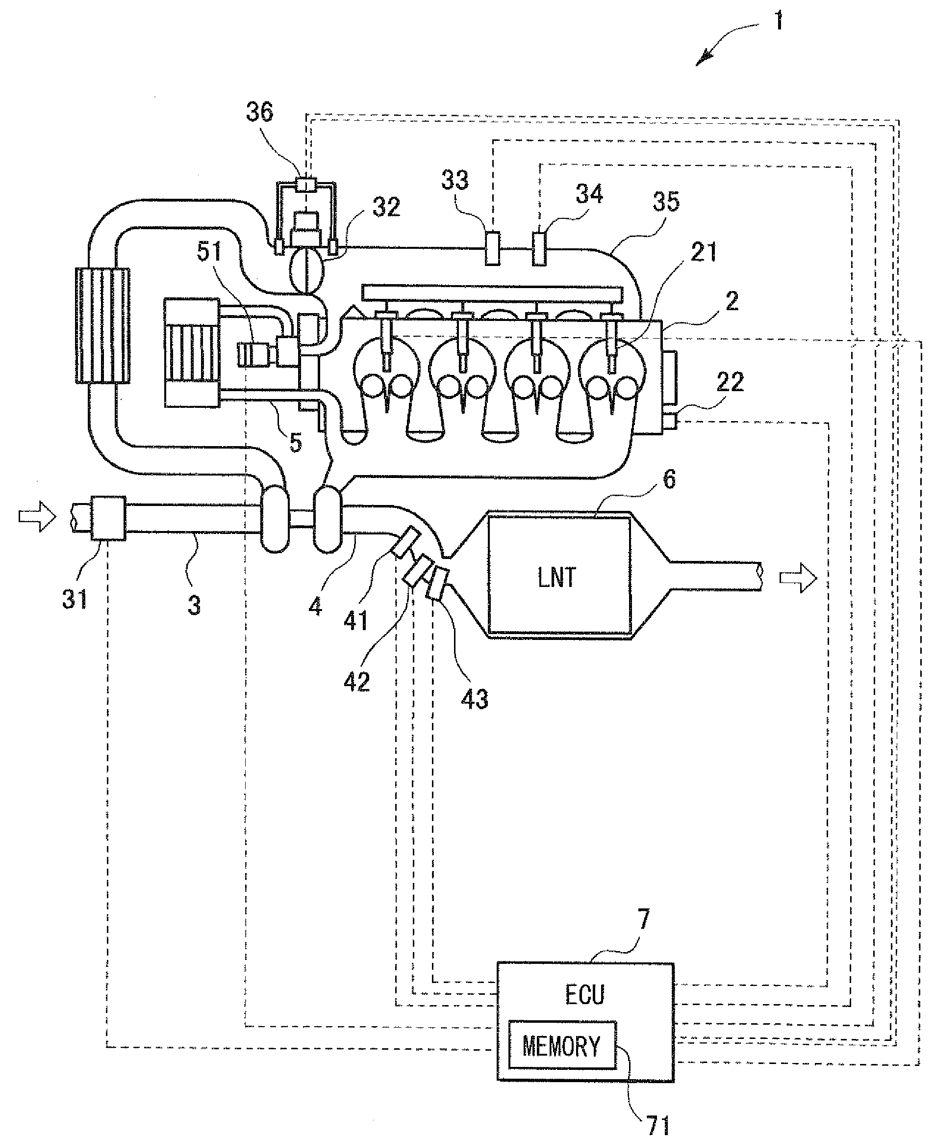
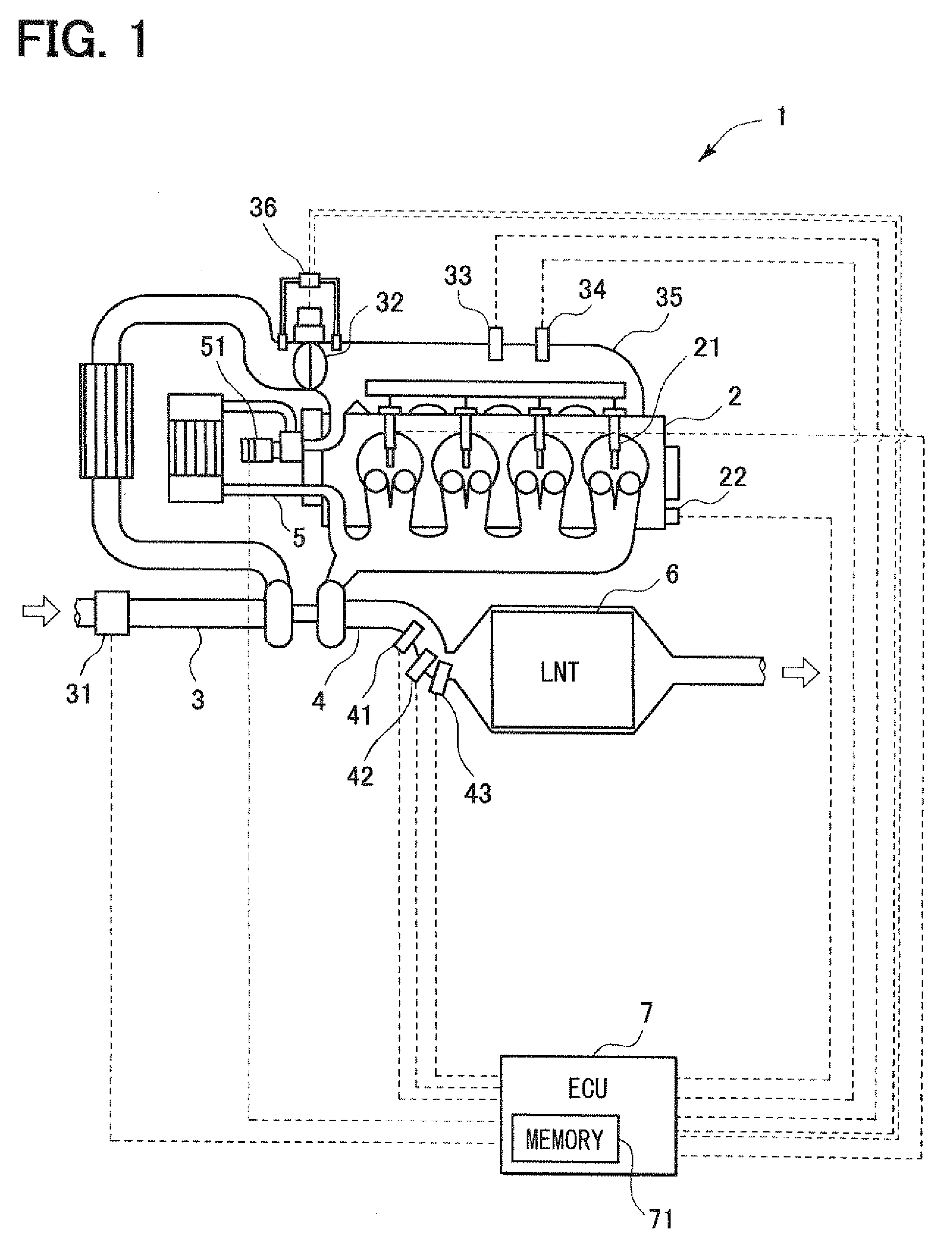
[0037]Hereafter, an embodiment of the present invention will be described with reference to the drawings. FIG. 1 is a schematic diagram showing a device configuration of a control device 1 of an internal combustion engine according to the present embodiment.

[0038]FIG. 1 shows an example of the control device 1 applied to a four-cylinder diesel engine 2 (hereafter, referred to simply as an engine). The internal combustion engine and the control device 1 shown in FIG. 1 mainly consist of an engine 2, an intake pipe 3, an exhaust pipe 4 and an exhaust gas recirculation pipe 5.

[0039]An air (a fresh air, an intake air) is supplied to the engine 2 from the intake pipe 3 via an intake manifold 35. An airflow meter 31 and an intake throttle 32 are provided to the intake pipe 3. The airflow meter 31 measures intake quantity. A mass flow rate per unit time may be measured as the intake quantity.

[0040]The intake quantity supplied to the engine 2 is increased / decreased by regulating an opening ...


PUM


Abstract

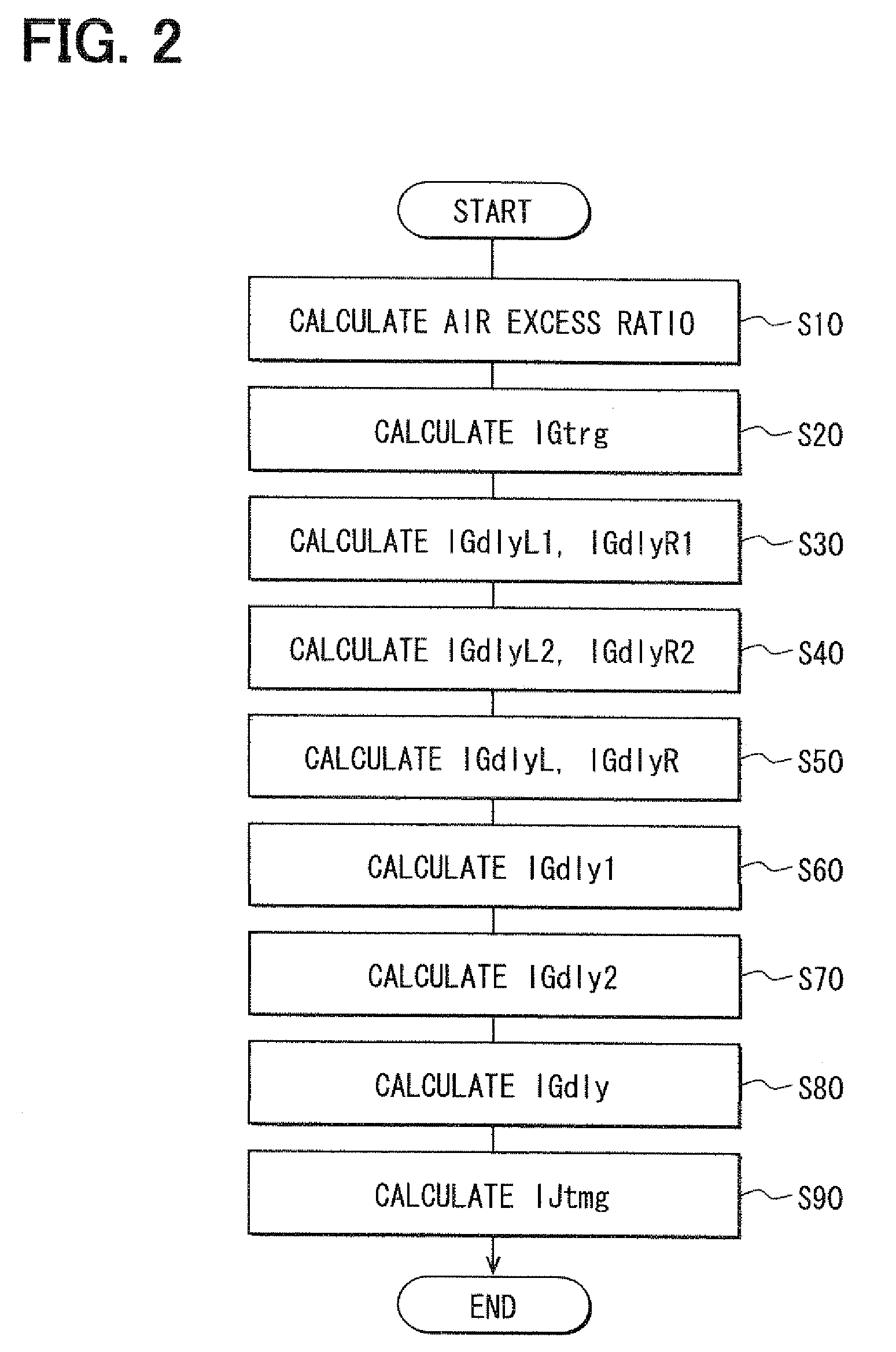
A control device of an internal combustion engine calculates ignition delays in lean combustion and rich combustion, standardizes the ignition delays based on ignition timing, and further standardizes the ignition delays based on injection quantity and injection timing of pilot injection respectively. The control device calculates a present ignition delay by linear interpolation of the standardized ignition delays in the lean combustion and the rich combustion. Moreover, the control device corrects the present ignition delay with the ignition timing and further corrects the present ignition delay with the injection quantity and the injection timing of the pilot injection. The control device calculates a command value of the injection timing by subtracting the corrected present ignition delay from target ignition timing.

Description

CROSS REFERENCE TO RELATED APPLICATION[0001]This application is based on and incorporates herein by reference Japanese Patent Application No. 2008-117458 filed on Apr. 28, 2008.BACKGROUND OF THE INVENTION[0002]1. Field of the Invention[0003]The present invention relates to a control device of an internal combustion engine.[0004]2. Description of Related Art[0005]An internal combustion engine such as a diesel engine that basically performs lean combustion at an air-fuel ratio higher than the theoretical air-fuel ratio frequently switches combustion to rich combustion at an air-fuel ratio equal to or lower than the theoretical air-fuel ratio. For example, in the case where an exhaust pipe is equipped with a NOx catalyst (LNT: a lean NOx trap) to purify nitrogen oxides (NOx) discharged from the engine, the NOx is occluded to the LNT under a lean atmosphere. Then, after an interval, the atmosphere is switched to a rich atmosphere to reduce the occluded NOx to harmless nitrogen. Also in ...

Claims


Application Information

Patent Timeline
IPC IPC(8): F02P5/04F02M25/07
CPCF01N3/0814Y02T10/44F02B37/00F02D37/02F02D41/00F02D41/0072F02D41/1446F02D41/1448F02D41/1458F02D41/403F02D2200/0411F02M25/0707F02M25/0713F02M25/0727F02B29/0406F02M26/05F02M26/10F02M26/23Y02T10/40
Inventor KAWAMURA, JUNYOKOYAMA, MASAKUNI
Owner DENSO CORP
Learn More