Nozzle with fluted tube

a technology of fluted tubes and nozzles, which is applied in the direction of engine starters, turbine/propulsion engine ignition, turbine/propulsion fuel heating, etc., can solve the problems of affecting the efficiency or usability of injectors, affecting the air flow to the combustor, and occupying valuable space in and around the combustion chamber of heat shield assemblies

Inactive Publication Date: 2005-07-12
PARKER INTANGIBLES LLC
View PDF8 Cites 69 Cited by
  • Summary
  • Abstract
  • Description
  • Claims
  • Application Information

AI Technical Summary

Benefits of technology

[0010]The present invention provides a new and unique fuel injector, particularly for gas turbine applications in aircraft engines, where the fuel injector delivers fuel to a combustion chamber for operation of the gas turbine engine, and does not require bulky heatshielding and prevents, or at least reduces, coking in the injector. The present invention is particularly useful for applications where a secondary (non-continuous or reduced) fuel flow surrounds a primary (continuous) fuel flow through the injector.

Problems solved by technology

The deposits can build up and restrict fuel flow through the fuel passage and the fuel nozzle, rendering the injector inefficient or unusable.
As is known, the heat shield assemblies can take up valuable space in and around the combustion chamber, block air flow to the combustor, and add weight to the engine.
They can also be labor-intensive, time-consuming and expensive to assemble and repair.
Large, bulky heatshields can be undesirable with current industry demands requiring reduced cost, smaller injector size (“envelope”) and reduced weight for more efficient operation.
As can be appreciated, such efforts add still further cost and complexity to the fuel injector.
Thus, it is a continuing challenge to develop fuel injectors to properly deliver fuel to a combustion chamber for operation of the gas turbine engine, where the injectors do not require bulky heatshielding and prevent, or at least reduce, coking in the injector during all aspects of engine operation.

Method used


Image

  • Nozzle with fluted tube
  • Nozzle with fluted tube
  • Nozzle with fluted tube

Examples


Embodiment Construction

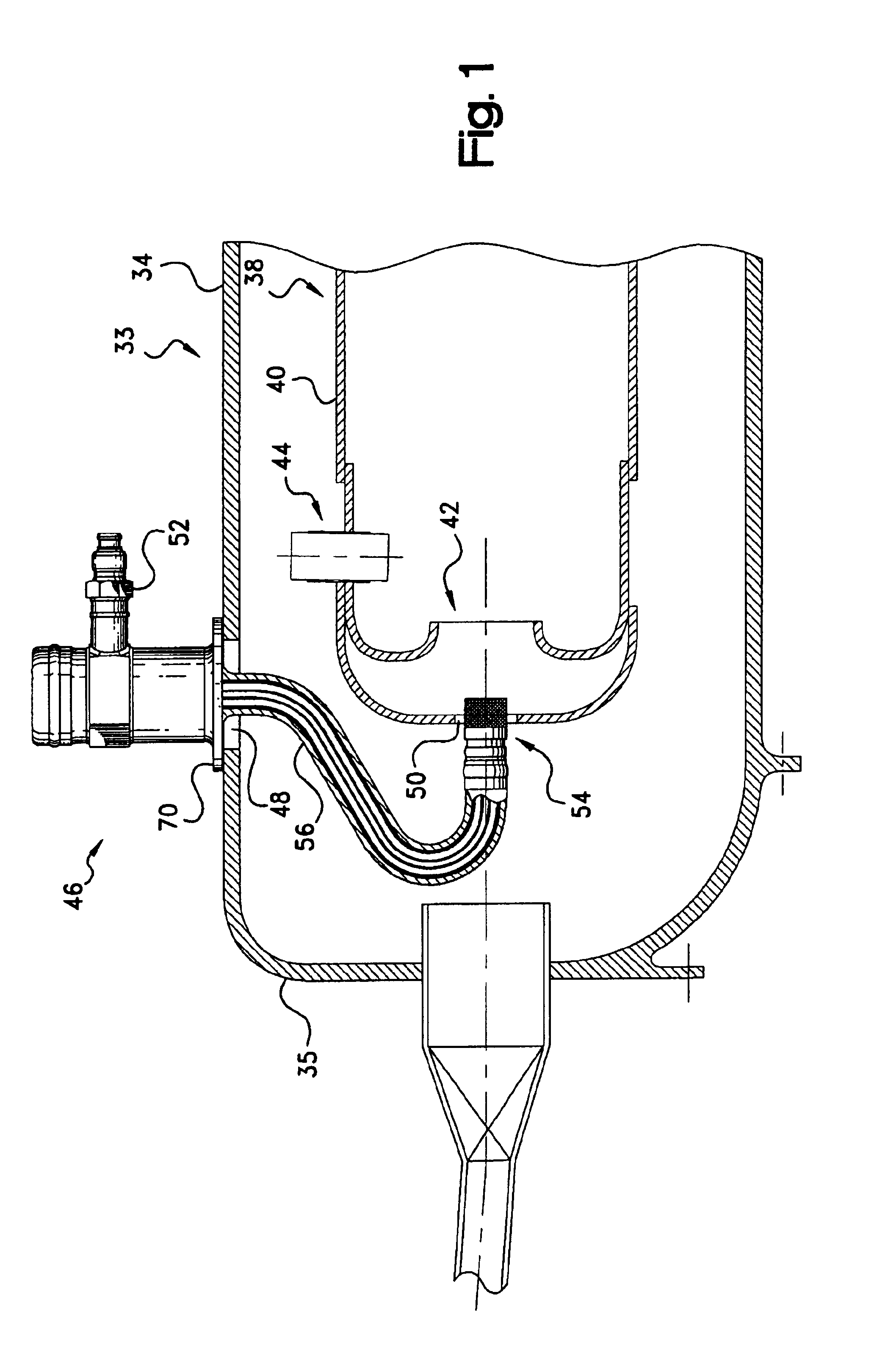
[0021]Referring initially to FIG. 1, a gas turbine engine for an aircraft is illustrated generally at 33. The gas turbine engine 33 includes an outer casing 34 extending forwardly of an air diffuser 35. The casing and diffuser enclose a combustor, indicated generally at 38, for containment of burning fuel. The combustor 38 includes a liner 40 and a combustor dome, indicated generally at 42. An igniter, indicated generally at 44, is mounted to the combustor 38 and extends inwardly into the combustor for igniting fuel. The above components are conventional in the art and their manufacture and fabrication are well known. It should be appreciated that this is only a schematic illustration of a gas turbine engine for the present invention, and that the actual engine structure depends upon the particular application.

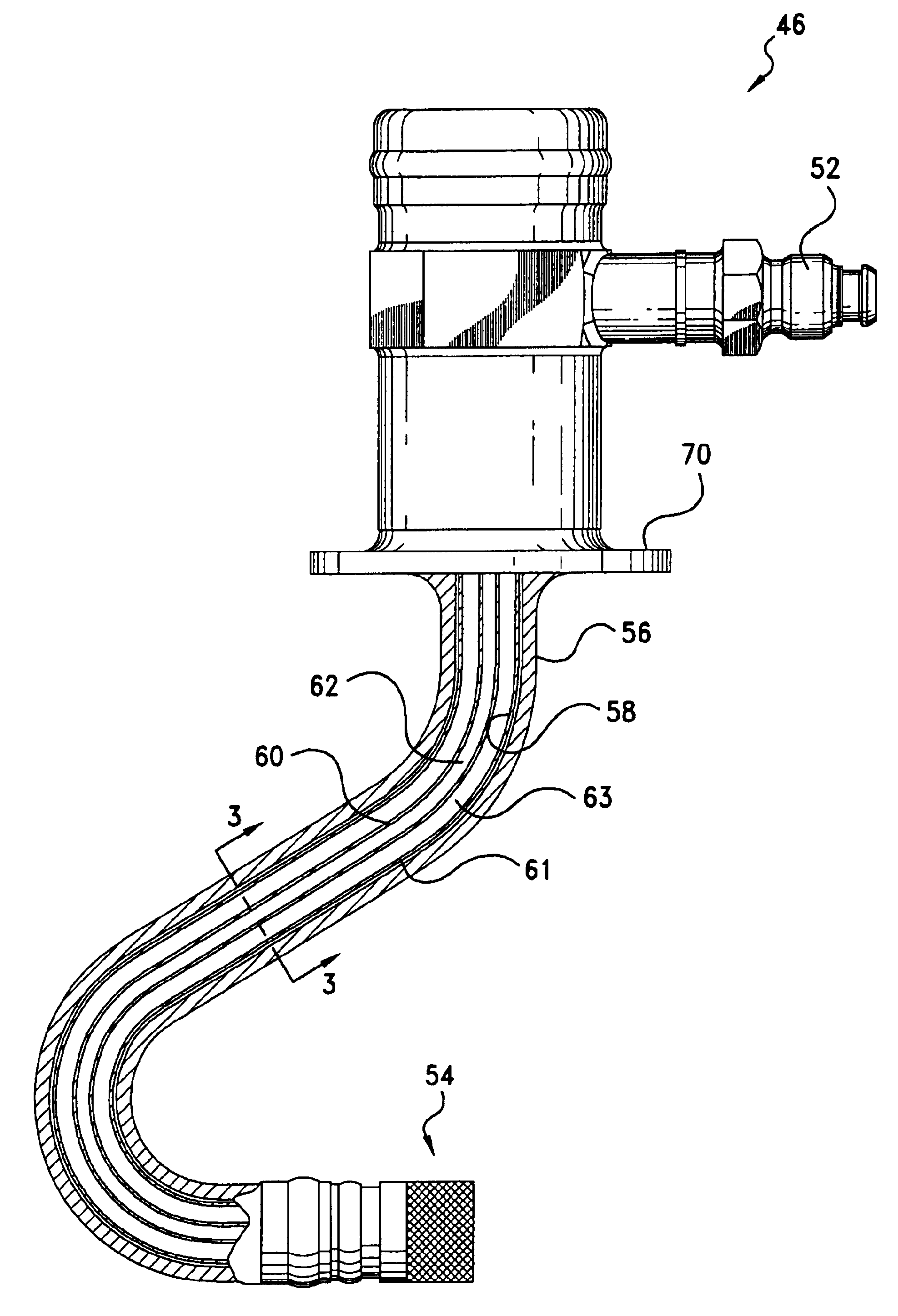
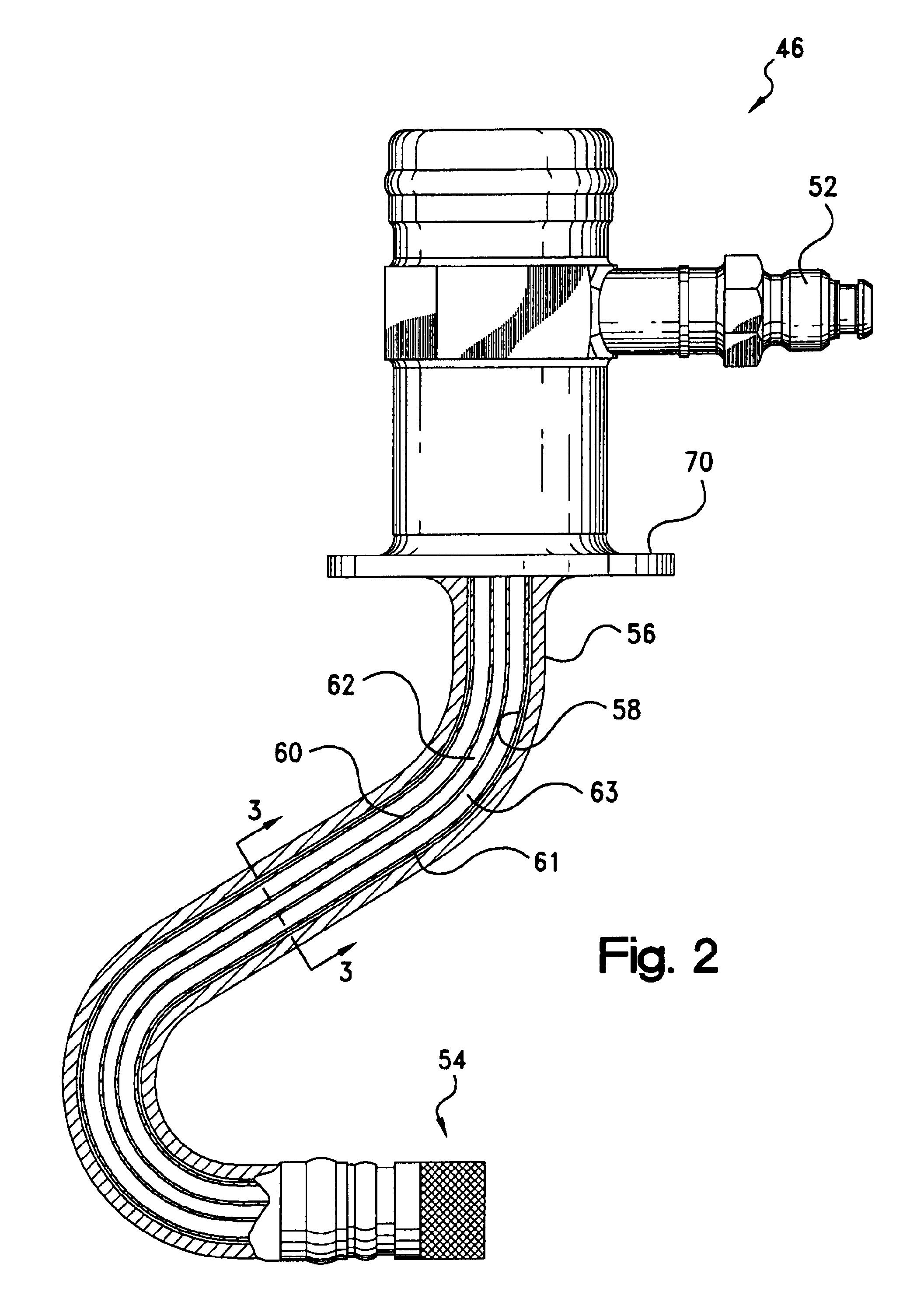
[0022]A fuel injector, indicated generally at 46, is received within an aperture 48 formed in the engine casing and extends inwardly through an aperture 50 in the combustor li...


PUM


Abstract

A fuel injector for gas turbine engines includes an inlet fitting, a housing stem, and a spray nozzle. A pair of fuel passages in the stem deliver fuel in a primary (continuous) flow and a secondary (non-continuous or reduced) flow to primary and secondary discharge orifices in the nozzle. The fuel passages are defined by inner and outer concentric conduits, with the primary flow directed through the inner conduit, and the secondary flow directed through the outer conduit. Fins are provided unitary with the inner conduit along the length of the housing stem, and are fixed at their radial outer ends to the outer conduit. The fins provide structural support and thermally connect the inner and outer conduits. During low power operation, the fins transfer heat energy between the outer conduit to the inner conduit to cool the outer conduit and thermally protect the fuel in the secondary fuel passage.

Description

CROSS-REFERENCE TO RELATED CASES[0001]The present application claims the benefit of the filing date of U.S. Provisional Application Ser. No. 60 / 368,620; filed Mar. 28, 2002, the disclosure of which is expressly incorporated herein by reference.FIELD OF THE INVENTION[0002]The present invention relates to fluid delivery systems, and more particularly to injectors useful for dispensing liquid fuel for combustion in gas turbine engines.BACKGROUND OF THE INVENTION[0003]Fuel injectors useful for applications such as gas turbine combustion engines direct pressurized fuel from a manifold to one or more combustion chambers. Fuel injectors also function to prepare the fuel for mixing with air prior to combustion. Each injector typically includes an inlet fitting connected to the manifold, a tubular stem or extension connected at one end to the fitting, and one or more spray nozzles connected to the other end of the stem for directing the fuel into the combustion chamber. A fuel passage (e.g.,...

Claims


Application Information

Patent Timeline
Patent Type & Authority Patents(United States)
IPC IPC(8): F02C7/22F02C7/224
CPCF02C7/224
Inventor RUNKLE, BRYAN T.QIAN, JIEHARDING, CURTIS F.
Owner PARKER INTANGIBLES LLC
Why Eureka
Try Eureka