A bearing hinged support

A technology of hinge support and bearing seat, applied in the direction of bearing components, shafts and bearings, engine components, etc., can solve the problems of reduced bearing capacity, large force, consumption, etc., and achieve the effect of increasing drive energy consumption and reasonable structure

Inactive Publication Date: 2012-12-19
北京摩诘创新科技股份有限公司
View PDF6 Cites 0 Cited by
  • Summary
  • Abstract
  • Description
  • Claims
  • Application Information

AI Technical Summary

Problems solved by technology

After one end of the electric cylinder is connected to the upper hinge support assembly, it is connected to the upper bottom plate of the platform through the upper hinge support connection seat, and the other end of the electric cylinder assembly is connected to the lower bottom plate of the platform through the lower hinge support assembly. The hinge support to be used adopts the main shaft of equal diameter, according to the Image 6 According to the analysis of the force on the equal-diameter main shaft, it can be seen that the force on each part of the hinge support is quite different when it is working, and there is a large force at the load point of the main shaft, which is also the cause of the main shaft. The main force of the bending deformation of the rotating shaft is less when it is close to the two ends of the main rotating shaft. When increasing the load-bearing load, if the diameter of the entire main rotating shaft is increased with equal diameters, the support of the main rotating shaft can be enhanced to a certain extent Strength; at the same time, this method of increasing the structure of the main shaft with equal diameter will substantially increase the weight of the entire main shaft and the contact area between the main shaft end and the sliding bearing, thereby increasing the friction
Due to the sliding fit between the main shaft and the bearing seats at both ends, plus the objects on the moving platform can produce more than ten tons of support weight, if you want to manipulate the main shaft to rotate to change the support angle, you need to overcome the problems at the end of the main shaft. The larger force generated on the surface will consume a larger driving force
[0004] At the same time, the above-mentioned shaft support heavy-duty bearing adopts a traditional lubricating oil film, which is prone to failure when it runs for a long time, and will cause wear between the shaft and the sliding bearing, which will affect the supporting capacity of the shaft end, resulting in a reduction in the load-carrying capacity. Service life of plain bearings

Method used


Image

  • A bearing hinged support
  • A bearing hinged support
  • A bearing hinged support

Examples


Embodiment Construction

[0036] In order to make the object, technical solution and advantages of the present invention clearer, the implementation manner of the present invention will be further described in detail below in conjunction with the accompanying drawings.

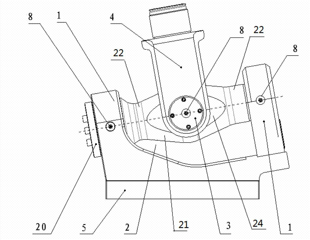
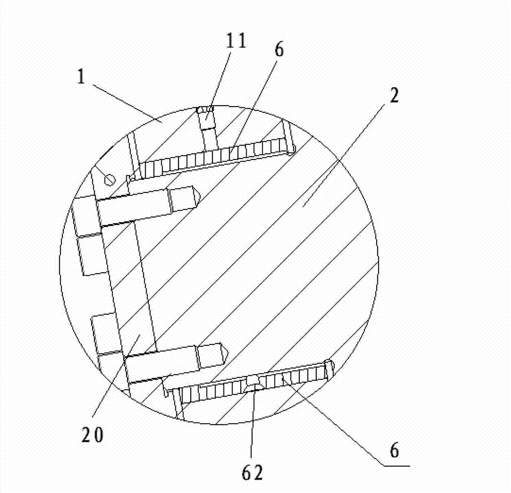
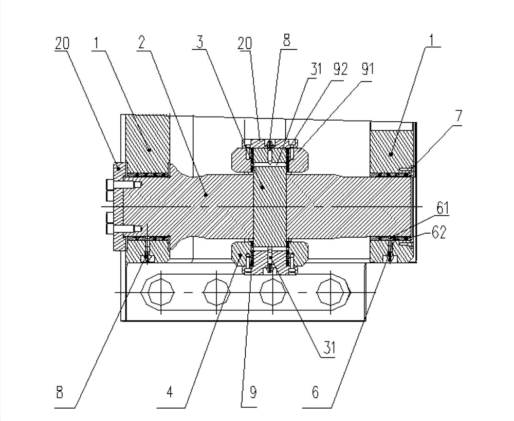
[0037] Such as figure 1 , figure 2 and image 3 As shown, the present invention provides a load-bearing hinge support, including a bearing seat 1, a main shaft 2, an auxiliary shaft 3, a support shaft 4 and a support 5, the bearing seat 1 is fixed at both ends of the support 5, and the main shaft 2 It includes a bearing shaft and a non-bearing shaft connected to each other. The non-bearing shaft is arranged at both ends of the bearing shaft, and its end is connected with the bearing seat 1, and a through hole 23 is formed along the radial direction of the bearing shaft; the non-bearing shaft 22 The two ends of the bearing seat 1 are respectively rotated and matched, and the non-loading shaft 22 forms a through hole 23 in the radial...


PUM


Abstract

The invention discloses a bearing hinged support which comprises a bearing pedestal (1), a main rotating shaft (2), an auxiliary rotating shaft (3) and a supporting shaft (4). The main rotating shaft (2) comprises a bearing shaft and non-bearing shafts connected with each other, wherein the non-bearing shafts (22) are arranged at two ends of the bearing shaft (21), are connected with the bearing pedestal (1) the end parts thereof, and form a through-hole (23) along a radial direction of the bearing shaft (21). The auxiliary rotating shaft (3) passes through the through-hole and the two ends of the auxiliary rotating shaft extend to the outside of the bearing shaft (21). The supporting shaft (4) is connected with two ends of the auxiliary rotating shaft (3), and rotates around a center line of the through-hole. Shaft diameter at a position of the bearing shaft is greater than that at a position of the non-bearing shafts. Through changing structure of the bearing main rotating shaft of the hinged support, force can be relatively reasonable when the support bears, and weight of the hinged support is not obviously increased while bearing capacity of the main rotating shaft is enhanced, thereby improving service life the main rotating shaft.

Description

technical field [0001] The invention relates to a load-bearing hinge support. Background technique [0002] The design load of the standard two-degree-of-freedom motion hinge support is relatively small. According to its structure, when the load-bearing load is to be increased, the diameter of the rotating shaft needs to be increased accordingly, which will inevitably cause a large waste of materials. At the same time, the weight of the hinge support The increase may also increase the load to a certain extent, resulting in increased energy consumption. [0003] Chinese patent document CN201723926U discloses a six-degree-of-freedom electromechanical motion platform, including a platform upper base, a platform lower base, and six electric cylinder assemblies connected between the platform upper base and the platform lower base. After one end of the electric cylinder is connected to the upper hinge support assembly, it is connected to the upper bottom plate of the platform thr...

Claims


Application Information

Patent Timeline
Patent Type & Authority Applications(China)
IPC IPC(8): F16C11/04F16C33/04F16N1/00
Inventor 刘文冬崔明宝张蔚萍王宝奇
Owner 北京摩诘创新科技股份有限公司
Why Eureka
Try Eureka