Ice maker fill tube assembly

a technology for filling tubes and ice makers, which is applied in the field of refrigerators, can solve the problems of clogging of the tube, tube may freeze, and still a possibility

Inactive Publication Date: 2005-07-12
MAYTAG
View PDF38 Cites 5 Cited by
  • Summary
  • Abstract
  • Description
  • Claims
  • Application Information

AI Technical Summary

Benefits of technology

[0009]The present invention is directed to a fill tube arranged for an ice maker assembly in a freezer compartment of a refrigerator, wherein the fill tube functions to transport liquid from a reservoir to a mold. The freezer includes an outer wall spaced apart from an inner wall, and a plenum formed therebetween. An opening is formed within the inner wall, through which the fill tube extends with a desired clearance. Warm air generated by a defrost cycle passes through the clearance in the inner wall and around the fill tube, thereby warming the fill tube.
[0010]In addition, the fill tube is formed with vents to allow active ventilation of the fill tube in order to prevent ice formation within the fill tube. Particularly, warm air generated by a defrost cycle is allowed to enter the vents formed within the fill tube to prevent freezing of the fill tube. The fill tube is also exposed to dehumidified freezer air from behind the inner wall. The dehumidified freezer air helps to prevent ice formation on the surface of the fill tube, as well as ice restrictions within the fill tube.

Problems solved by technology

Since the ice maker fill tube extends into the freezer compartment, a problem exists in that water can freeze within the tube and lead to clogging of the tube.
In the arrangement of the '644 patent, there is still a possibility that the tube may freeze.
Therefore, any heat provided by the outer case may not be sufficient to prevent freezing of other portions of the fill tube.
Further, the tube is surrounded by foam and may be difficult to remove if it is necessary to clear an ice blockage within the tube.
However, this arrangement adds significantly to the costs associated with manufacturing the fill tube and ice maker.
Additionally, the heater arrangement will certainly affect installation and repair costs associated with the fill tube and ice maker.

Method used


Image

  • Ice maker fill tube assembly
  • Ice maker fill tube assembly
  • Ice maker fill tube assembly

Examples


Embodiment Construction

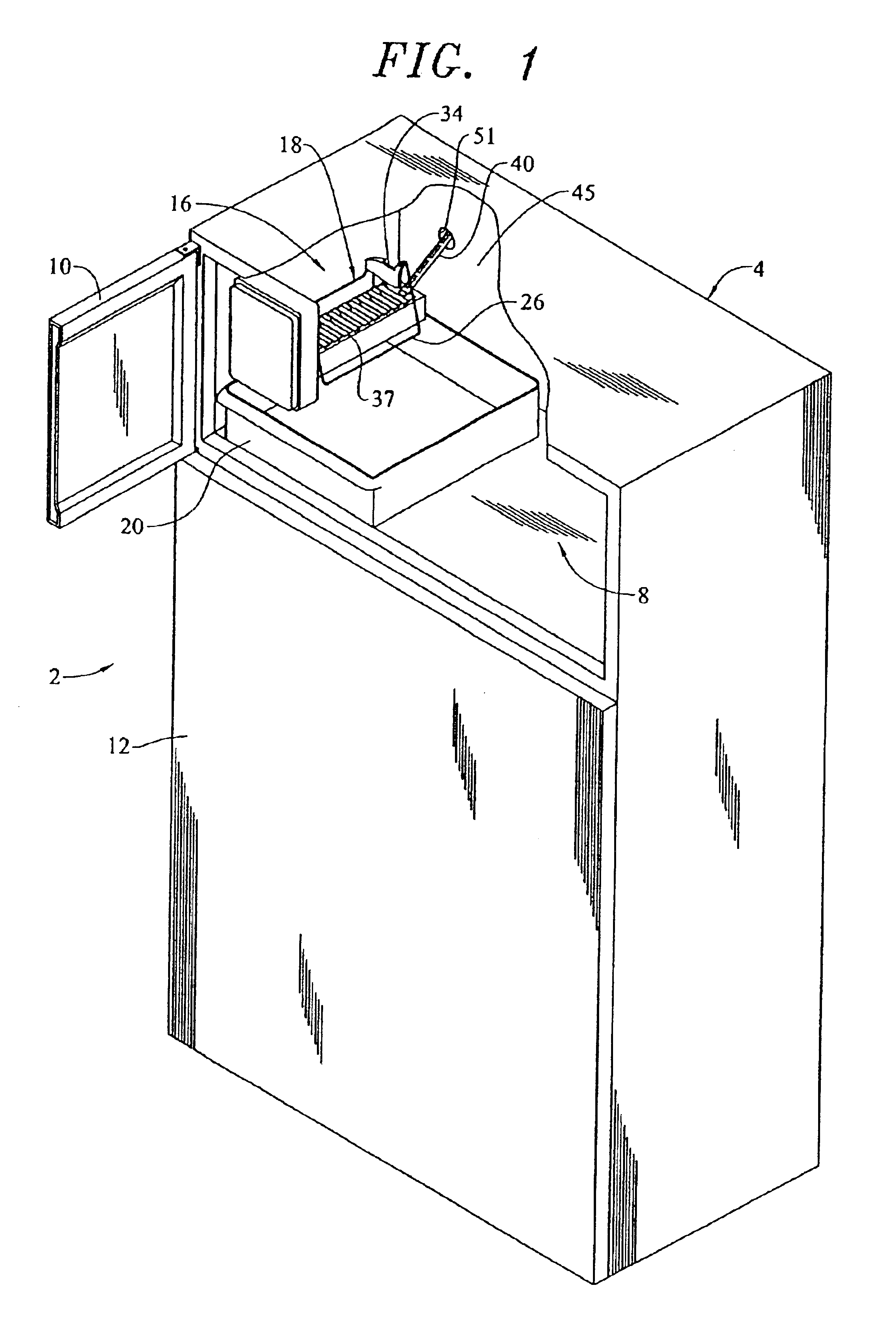
[0015]With initial reference to FIG. 1, a refrigerator 2 includes a cabinet 4 within which is defined a freezer compartment 8. Freezer compartment 8 can be selectively accessed through the pivoting of a freezer door 10. Also provided is a fresh food door 12 which enables access to a fresh food compartment (not shown). As shown, refrigerator 2 constitutes a top-mount model. However, as will become fully evident below, the present invention is equally applicable to various types of refrigerators, including side-by-side models.

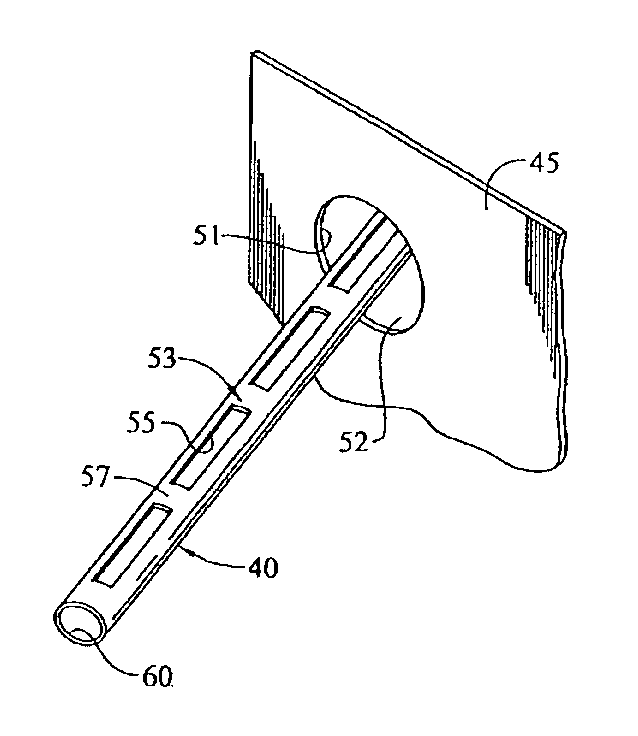
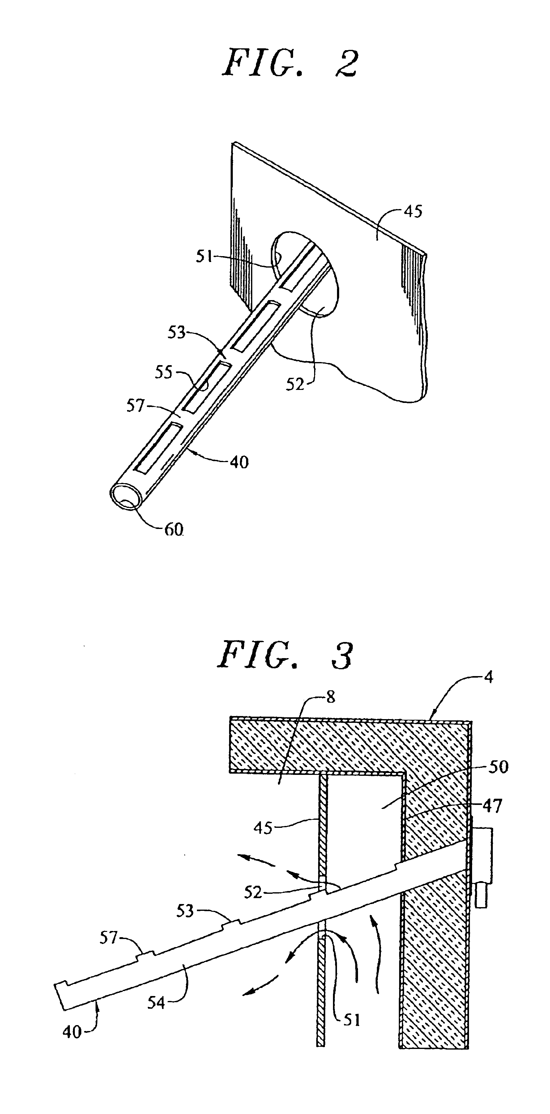
[0016]Arranged within freezer compartment 8 is an ice maker assembly 16. In a manner known in the art, ice maker assembly 16 includes an ice maker unit 18 and an ice storage bin 20. Ice maker unit 18 is shown to include a bale arm 26 which is pivotable upward and downward based on the amount of ice retained in storage bin 20. Bale arm 26 is actually pivotally connected to a switch arm 34.

[0017]Ice maker unit 18 also includes an ice mold 37. In general, this const...


PUM


Abstract

An ice maker assembly in a refrigerator freezer includes a fill tube for transporting liquid to a mold. The freezer includes an outer wall spaced apart from an inner wall, with a plenum formed therebetween. An opening is formed within the inner wall, through which the fill tube extends with a clearance. Warm air generated by a defrost cycle passes through the clearance in the inner wall and around the fill tube, thereby warming the fill tube. In addition, the fill tube includes vents formed therein to allow active ventilation of the fill tube and to prevent ice formation within the fill tube.

Description

CROSS-REFERENCE TO RELATED APPLICATIONS[0001]This application represents a continuation of U.S. patent application Ser. No. 10 / 355,085 filed Jan. 31, 2003, now U.S. Pat No. 6,810,680.BACKGROUND OF THE INVENTION[0002]1. Field of the Invention[0003]The present invention pertains to the art of refrigerators, and, more particularly, to a fill tube arrangement for an ice maker assembly provided in a freezer of a refrigerator.[0004]2. Discussion of the Prior Art[0005]Providing automatic ice makers in household refrigerators has become extremely commonplace. Ice makers typically include a tray that is filled by a water fill tube extending through a wall of a freezer compartment.[0006]Since the ice maker fill tube extends into the freezer compartment, a problem exists in that water can freeze within the tube and lead to clogging of the tube. Several attempts have been made to solve this problem. For example, U.S. Pat. No. 4,020,644 discloses a water supply line that is maintained in contact...

Claims


Application Information

Patent Timeline
Patent Type & Authority Patents(United States)
IPC IPC(8): F25C1/04F25D11/02
CPCF25C1/04F25C2400/10F25C2400/14F25D11/02F25D2400/04
Inventor POHL, DOUGLAS A.VESTAL, WILLIAM JAMESWIDMER, KENTON JOHN
Owner MAYTAG
Why Eureka
Try Eureka