There have been many incidents where sanitary processes have failed, resulting in loss of product.
In some cases, harm to consumers occurs.
In many other instances; however, the source of
contamination has been traced back to drain valves, which have not been properly cleaned, and in many cases where procedures specify it, sterilized between production runs.
The causes for these failures, almost without exception, relate to material accumulation in low, undrainable
pooling areas and in tight crevice areas, particularly those associated with
moving parts such as sliding or rotating O-ring seals.
Cleaning and sterilizing followed by the
initiation of process production may cause large deposits or accumulations to soften and slough or break off, getting blended into downstream process materials, representing significant
contamination to the process.
These large deposits are of particular concern because they represent
contamination threats large enough to significantly affect product quality and process outcome even for processes traditionally considered very robust, such as some food, beverage and
chemical production.
If gone undetected, product
exposure can, in some cases, be harmful or even fatal.
At some point, however, increasing human intervention becomes impractical and cost-prohibitive.
Specifically, the performance of current valve designs in sanitary process applications where valve maintenance efforts between production runs has been practically limited to in-situ cleaning, rinsing and
steam sterilization.
Even though many of the new sanitary processes being implemented include state-of-the-art weir diaphragm and radial diaphragm drain valve designs, failures still persist in these processes, albeit at a decreased rate.
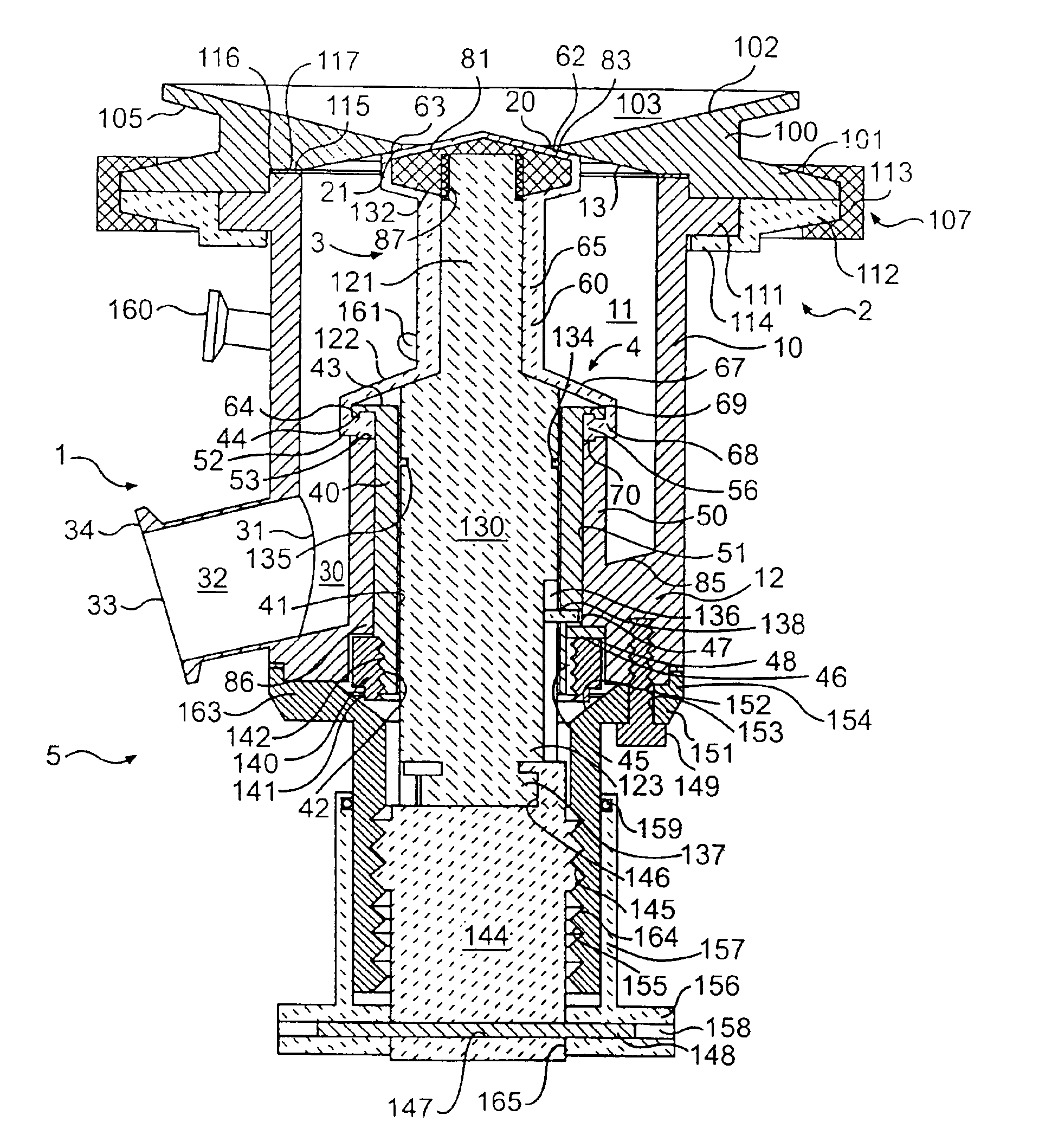
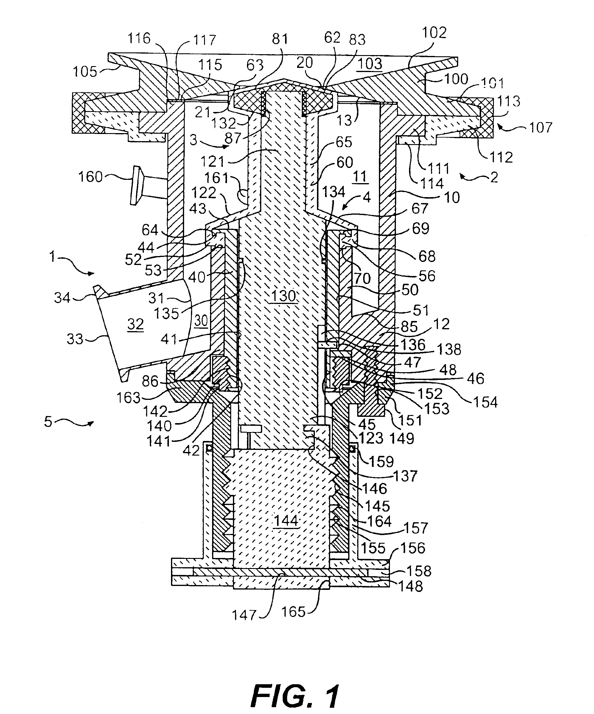
As a result, the thickness of the bottom wall between the first (process) and second (non-process) sides form the wall of a well which is not possible to drain and serves to entrap and shelter process material, cleaning agents,
rinse water and steam condensate.
The problem associated with valves equipped with O-ring seals is, generally speaking, just the opposite.
Although the volume of the well tends to be much less, effective access for proper CIP and SIP procedure execution is not consistently possible.
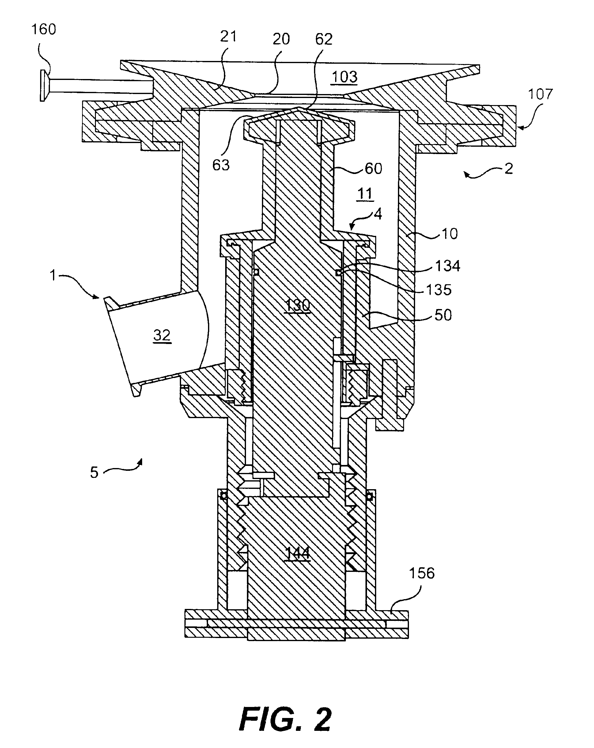
Another problem area of valves associated with the design of bottom seal devices is their general tendency to have at least partially flat bottom walls to the valve internal cavity.
While these walls may make these valves easier to fabricate, flat surfaces do not contribute to achieving positive drainage of materials from within the valve.
Standing fluids, in many instances, can be as large of a
threat of contamination as entrapped material, sometimes more because of the presence of large amounts of water, an important ingredient for microbial proliferation.

