
Sanitary drain valve design

a technology of sanitary drain valve and design, which is applied in the direction of diaphragm valve, valve housing, engine diaphragm, etc., can solve the problems of loss of product, harm to consumers, and contamination source traceability, and achieve the effects of improving the ability of cleanability and drainability, and good characteristics of process isolation and in-situ cleanability

Inactive Publication Date: 2005-10-27
NEWBERG DOUGLAS A
View PDF23 Cites 2 Cited by
  • Summary
  • Abstract
  • Description
  • Claims
  • Application Information

AI Technical Summary

Benefits of technology

[0014] An object of the present invention is to provide an improved general valve design having good characteristics of process isolation and in-situ cleanability in many orientations as well as providing specific improvements in cleanability and drainability performance capabilities over the background art when used in conduit or tank bottom valve applications.
[0015] Another benefit of the present invention is an improved, free-draining, cleaner sealing arrangement for tulip, kettle and other O-ring-based seal designs, it also being possible to clean and sterilize the sealing arrangement from the back, non-process side independently from the process side on a descript or continuous basis, even while the valve is being operated.
[0016] A further object of the present invention is to provide a valve that can be mounted directly on the bottom of a tank, and, in the diaphragm configuration, can provide absolute isolation of the process from the valve components and the outside surrounding environment. Furthermore, in the case of o-ring designs, the present invention can provide a high degree of isolation of the process from the valve components and the outside surrounding environment.

Problems solved by technology

There have been many incidents where sanitary processes have failed, resulting in loss of product.
In some cases, harm to consumers occurs.
In many other instances; however, the source of contamination has been traced back to drain valves, which have not been properly cleaned, and in many cases where procedures specify it, sterilized between production runs.
The causes for these failures, almost without exception, relate to material accumulation in low, undrainable pooling areas and in tight crevice areas, particularly those associated with moving parts such as sliding or rotating O-ring seals.
Cleaning and sterilizing followed by the initiation of process production may cause large deposits or accumulations to soften and slough or break off, getting blended into downstream process materials, representing significant contamination to the process.
These large deposits are of particular concern because they represent contamination threats large enough to significantly affect product quality and process outcome even for processes traditionally considered very robust, such as some food, beverage and chemical production.
If gone undetected, product exposure can, in some cases, be harmful or even fatal.
At some point, however, increasing human intervention becomes impractical and cost-prohibitive.
Specifically, the performance of current valve designs in sanitary process applications where valve maintenance efforts between production runs has been practically limited to in-situ cleaning, rinsing and steam sterilization.
Even though many of the new sanitary processes being implemented include state-of-the-art weir diaphragm and radial diaphragm drain valve designs, failures still persist in these processes, albeit at a decreased rate.
As a result, the thickness of the bottom wall between the first (process) and second (non-process) sides form the wall of a well which is not possible to drain and serves to entrap and shelter process material, cleaning agents, rinse water and steam condensate.
The problem associated with valves equipped with O-ring seals is, generally speaking, just the opposite.
Although the volume of the well tends to be much less, effective access for proper CIP and SIP procedure execution is not consistently possible.
Another problem area of valves associated with the design of bottom seal devices is their general tendency to have at least partially flat bottom walls to the valve internal cavity.
While these walls may make these valves easier to fabricate, flat surfaces do not contribute to achieving positive drainage of materials from within the valve.
Standing fluids, in many instances, can be as large of a threat of contamination as entrapped material, sometimes more because of the presence of large amounts of water, an important ingredient for microbial proliferation.

Method used


Image

  • Sanitary drain valve design
  • Sanitary drain valve design
  • Sanitary drain valve design

Examples


Embodiment Construction

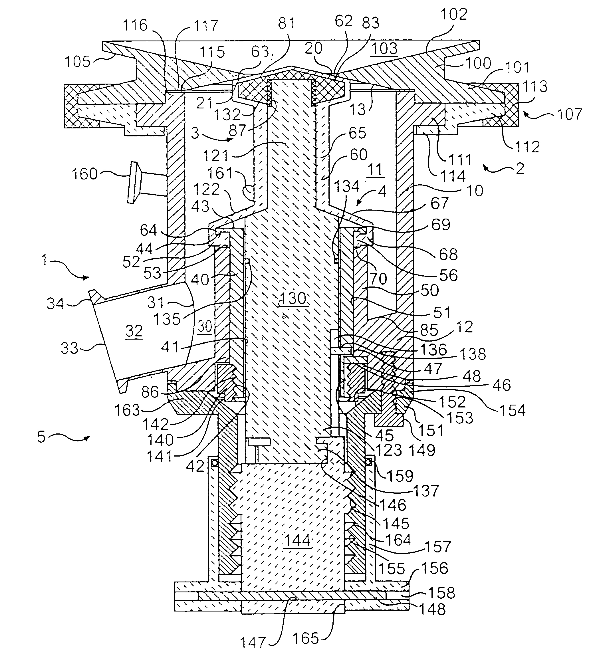
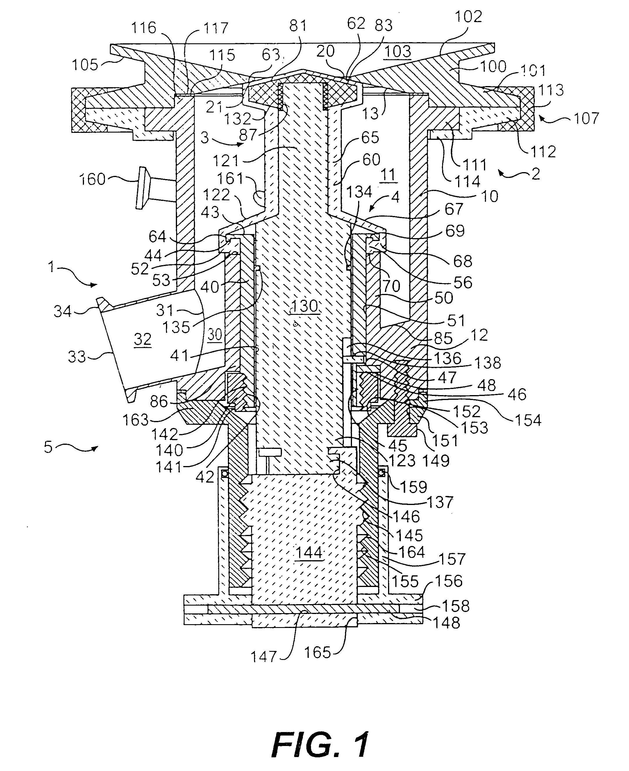
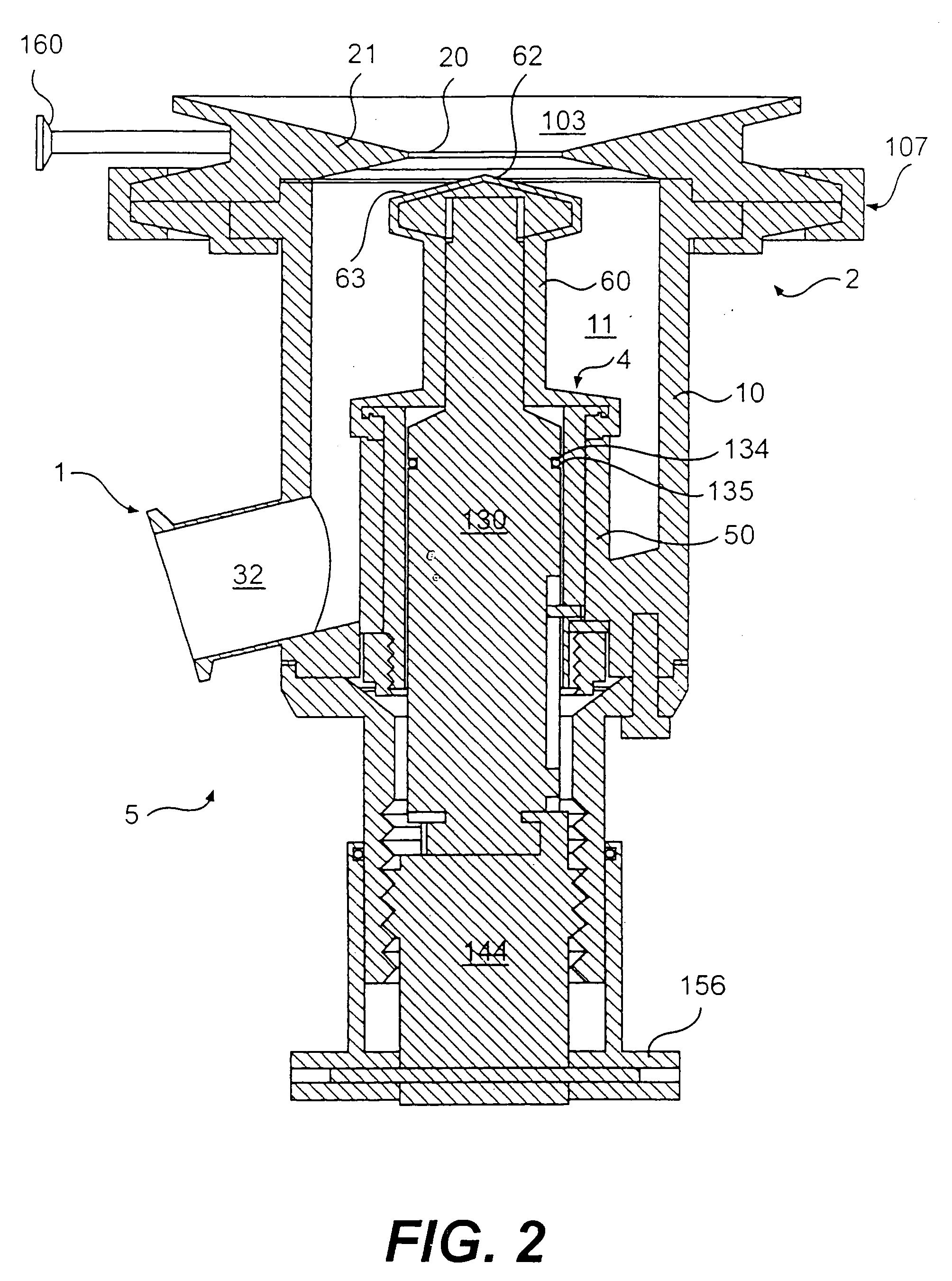
[0041] In general, the device of the present invention includes a valve body equipped with a manual, automated or combination actuator capable of moving a sealing tip attached to a valve operating rod reversibly into a sealing condition with a valve seat surrounding a first inlet flow passage into an internal cavity in the valve body. The valve body has at least one outlet flow passage placed at the bottom of the internal valve body cavity to receive drainage, the bottom preferably but not necessarily being cantilevered or otherwise formed so as to assist drainage down to at least one outlet flow passage. A seal is formed between the static valve body and the dynamic valve actuating rod in which, whether an O-ring seal or diaphragm seal is used, the interface between the sealing elements is carried out in a face-down configuration so as to create a self-draining sealing interface and to eliminate the pooling that is associated with sump or well areas that occur in the annular space ...


PUM


Abstract

A valve for sampling a process from a tank or conduit includes an internal cavity in communication with at least one inlet and an outlet. A valve actuating rod includes a sealing tip attached to one end thereof. The valve actuating rod is movable to open and close the inlet to the internal cavity. Furthermore, a seal is provided to isolate the valve actuating rod and the outside environment from the process. The seal is formed on the process side of the bottom wall of the internal cavity in order to ensure that the process material, cleaning material, steam, etc. drains completely out of the internal cavity of the valve.

Description

CROSS-REFERENCE TO RELATED APPLICATIONS [0001] This application is a Continuation of Co-pending application Ser. No. 10 / 633,358, filed Aug. 4, 2003, which is Continuation of application Ser. No. 10 / 290,542, filed on Nov. 8, 2002, now U.S. Pat. No. 6,601,823, which is a Divisional of U.S. application Ser. No. 09 / 801,783, filed on Mar. 9, 2001, now U.S. Pat. No. 6,491,283. The entirety of each of these applications is hereby incorporated by reference. This non-provisional application also claims priority under 35 U.S.C § 119(a) on U.S. Provisional Application No. 60 / 187,996 filed in on Mar. 9, 2000, the entirety of which is hereby incorporated by reference.BACKGROUND OF THE INVENTION [0002] 1. Field of the Invention [0003] The present invention is directed to an improved sanitary valve design. In particular, the present invention is directed to a sanitary valve design that allows for free-drainage of process and sterilizing and cleaning materials. [0004] 2. Description of Background A...

Claims


Application Information

Patent Timeline
Patent Type & Authority Applications(United States)
IPC IPC(8): F16K1/38F16K7/20F16K27/02F16K31/00
CPCF16K1/38F16K7/20F16K41/103F16K27/0254F16K27/07F16K27/0236
Inventor NEWBERG, DOUGLAS A.
Owner NEWBERG DOUGLAS A
Learn More