Collapsible compact carrier device with collapsible wheel construction

a compact carrier and collapsible technology, applied in the direction of trolley/perambulator with multiple axes, folding cycles, cycles, etc., can solve the problems of many detachable parts, no method for any of the wheels to fold or recess in a space saving manner, and little that is compact or space-saving in most of these devices

Inactive Publication Date: 2005-07-12
SHAPIRO RICHARD N
View PDF44 Cites 68 Cited by
  • Summary
  • Abstract
  • Description
  • Claims
  • Application Information

AI Technical Summary

Benefits of technology

[0037]In accordance with yet another related aspect of the invention, a carrier device is provided which comprises a carrier unit and at least two wheels supporting said carrier unit, said wheels being adapted for rolling movement along the ground so as to provide corresponding movement of the carrier unit, at least one of said wheels including a support axle mounted on said carrier unit so as to provide rotation of said at least one wheel about an axis defined by said support axle, and said device further comprising fixating means for fixating said wheel so as to prevent rotation thereof about the axis defined by said support axle. In one advantageous implementation of this aspect of the invention, the device includes a wheel support member, the support axle is mounted for axial movement within said wheel support member, the fixating means comprises at least one projection extending outwardly from said axle, and at least one recess included in said wheel support member and disposed relative to said axle such that through a combination of rotation and axial movement of said axle, said projection can be caused to engage in said recess to prevent further rotation of said wheel about said axis defined by said axle and such that through a combination of oppositely directed axial movement and rotation of said axle, said projection can be released from engagement with said recess so as to enable rotation of said wheel about said axis defined by said axle.
[0041]In one advantageous implementation of this embodiment which is applicable to other embodiments as well, said wheels are mounted on said base member by a wheel support member including means cooperating with said base member to provide a releasable snap in connection between said wheel support member and said base whereby release of said snap-in connection enables movement of said wheels between said first and second positions thereof.

Problems solved by technology

However, in actuality, there is little that is compact or space-saving in most of these devices which characteristically incorporate a fixed or one piece cargo area or “well,” and set of two or four wheels which are affixed to an axle, and which provide no method for any of the wheels to fold or recess in a space saving manner.
Most suffer from a number of problems, including those relating to difficulty of manufacture, the need for many detachable parts, or difficulty in use, i.e., the requirement for non-intuitive actions by a consumer in order to determine how to collapse or set-up the cart or wagon.
The primary deficiency of the devices of the Havlovitz Patents, despite their simplicity, is that the devices are not truly compact designs.
Moreover, in the latter patent, it is quite awkward for the consumer to fold the handle down, since this requires lifting of the entire cart off the ground to achieve the recess handle position.
It is believed that these deficiencies and disadvantages have prevented the manufacture of a truly compact, space saving wheeled device having a very thin profile.

Method used


Image

  • Collapsible compact carrier device with collapsible wheel construction
  • Collapsible compact carrier device with collapsible wheel construction
  • Collapsible compact carrier device with collapsible wheel construction

Examples


Embodiment Construction

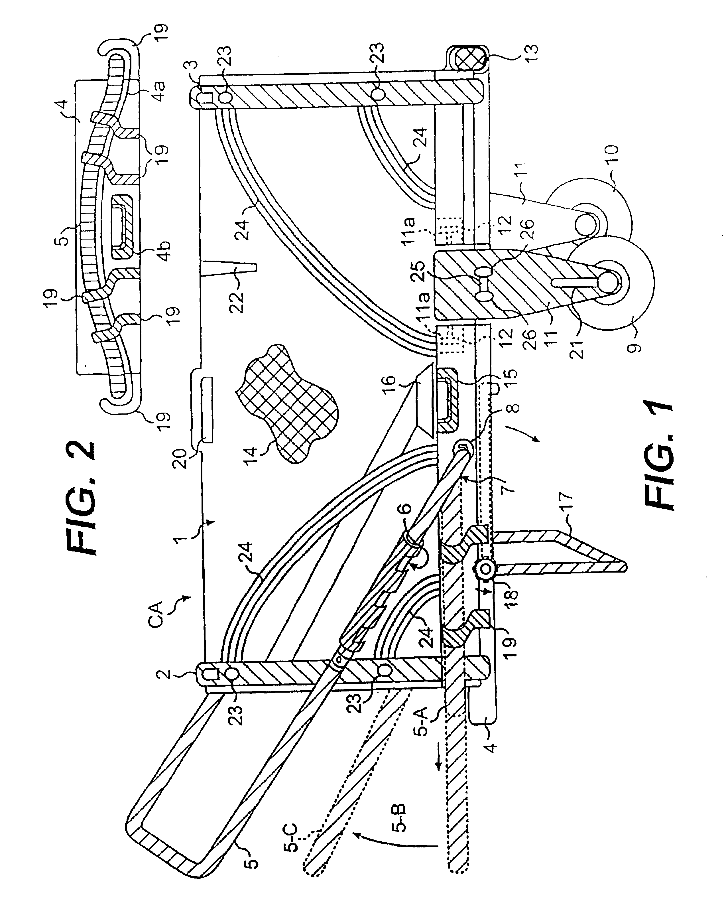
[0128]Referring to the drawings, FIG. 1 shows a two-wheeled cart, generally denoted CA, in a completely assembled or set-up state. The same cart CA, when folded, in the preferred embodiment, has a thickness of about the length of a credit card, and includes two side walls (one of which, denoted 1, is shown in FIG. 1) and front and rear walls 2 and 3. A base 4 has slightly elevated exterior base perimeter walls. A generally “U” shaped telescoping handle 5, constructed of extruded aluminum, another metal or any suitable plastic, is shown in solid lines in FIG. 1 in a final, upwardly secured, operative position of the handle 5 wherein handle 5 resiliently fits snugly into one or more sleeves or support sockets 6 molded into each side wall 1 of the cart. In operation, when the recessed, nested handle 5 (shown in dashed lines at 5-A) is pulled forward so that the handle 5 telescopes until it reaches a telescoped locked position, shown in dashed lines at 5-B, handle 5 is further lifted, a...


PUM


Abstract

A wheeled carrier device is provided which, in one embodiment, includes a plurality of foldable walls supported on a base member and movable between an erected state wherein the walls define a carrier space and a collapsed state wherein the walls are folded on top of the base member. The carrier device has at least two wheels and a wheel mounting assembly pivotably mounts the wheels on the device on opposite sides thereof such that, in one embodiment, the wheels are movable through 270° from a first, operative position wherein the wheels support the carrier device and a second, inoperative position wherein upon release of a latching mechanism the wheels are folded over on top of the folded walls in the collapsed state thereof. A handle is affixed to the carrier device and is movable between an operative state wherein the handle can be used to pull the carrier device and an inoperative state wherein the handle is stowed in substantially flush relation with the remainder of the carrier. In other embodiments, the wheels are pivoted through 90° to the stowed state thereof. In some embodiments, one or more of the wheels is rotatable about a support axle and various arrangements are provided for fixating the wheels against rotation. In other embodiments, some of the same basic principles are used in a collapsible stroller / jogger as well as in a collapsible “fun car” for children.

Description

CROSS REFERENCE TO OTHER APPLICATIONS[0001]This application is a division of U.S. Ser. No. 09 / 604,769 filed on Jun. 28, 2000 now U.S. Pat. No. 6,581,945, which is itself a continuation-in-part of U.S. application Ser. No. 09 / 271,274 filed on Mar. 17, 1999 now U.S. Pat. No. 6,220,611.FIELD OF THE INVENTION[0002]The present invention relates to wheeled carts, wagons and like carrier devices and, more particularly, to a collapsible wheeled carrier device which folds or collapses down to a very thin profile.BACKGROUND OF THE INVENTION[0003]Consumers have increasingly placed a premium on compact yet durable, space saving devices which move cargo, a fact that is easily demonstrated by the exponential growth in wheeled luggage devices using recessing, telescoping handles, as well as the ever expanding number of utility carts and four wheel wagons providing folding or recessing handles. It is often the stated object of many of these latter mentioned cart or wagon devices to provide for a si...

Claims


Application Information

Patent Timeline
Patent Type & Authority Patents(United States)
IPC IPC(8): B62B3/00B62B1/20B62B3/14B62B3/16B62B3/02B62B7/10B62B1/00B62B7/00B62B5/00B62B5/06
CPCB62B1/206B62B3/007B62B3/02B62B3/16B62B7/10B62B5/06B62B2205/04B62B2205/12
Inventor SHAPIRO, RICHARD N.
Owner SHAPIRO RICHARD N
Why Eureka
Try Eureka