
Semiconductor transistor using L-shaped spacer

Inactive Publication Date: 2005-07-12
SAMSUNG ELECTRONICS CO LTD
View PDF12 Cites 7 Cited by
  • Summary
  • Abstract
  • Description
  • Claims
  • Application Information

AI Technical Summary

Benefits of technology

[0022]The medium- and high-concentration junction areas are formed to make the medium-concentration junction area have a lower impurity concentration than the high-concentration junction area, using the protruding portions of the second and third spacers and the first insulating layer as an ion channeling barrier layer in the high-concentration ion implantation process. Preferably, the annealing process is a rapid thermal process (RTP).
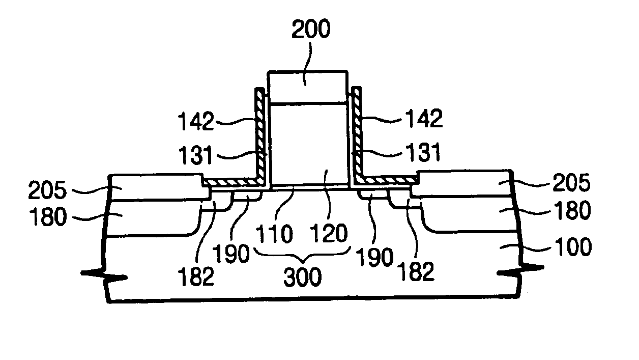
[0023]According to the present invention, a semiconductor transistor includes a gate pattern formed on a semiconductor substrate, an L-shaped third spacer, which is formed on a lateral surface of the gate pattern and has a horizontal protruding portion, an L-shaped fourth spacer having a sidewall between a sidewall of the third spacer and the gate pattern and a horizontal protruding portion between the protruding portion of the third spacer and the substrate, a high-concentration junction area formed in the substrate beyond the third spacer, a low-concen

Problems solved by technology

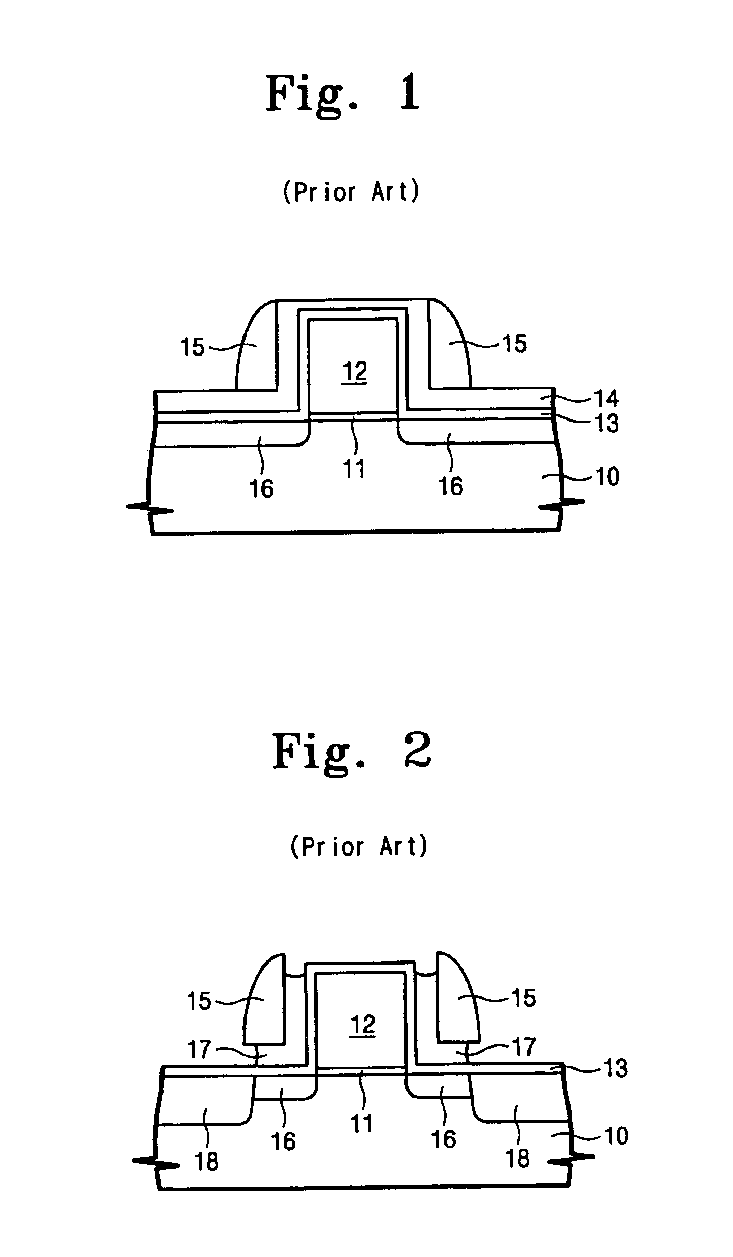
Unfortunately, the resistance of a source / drain region is high due to a low impurity concentration of the low-concentration junction area 16.
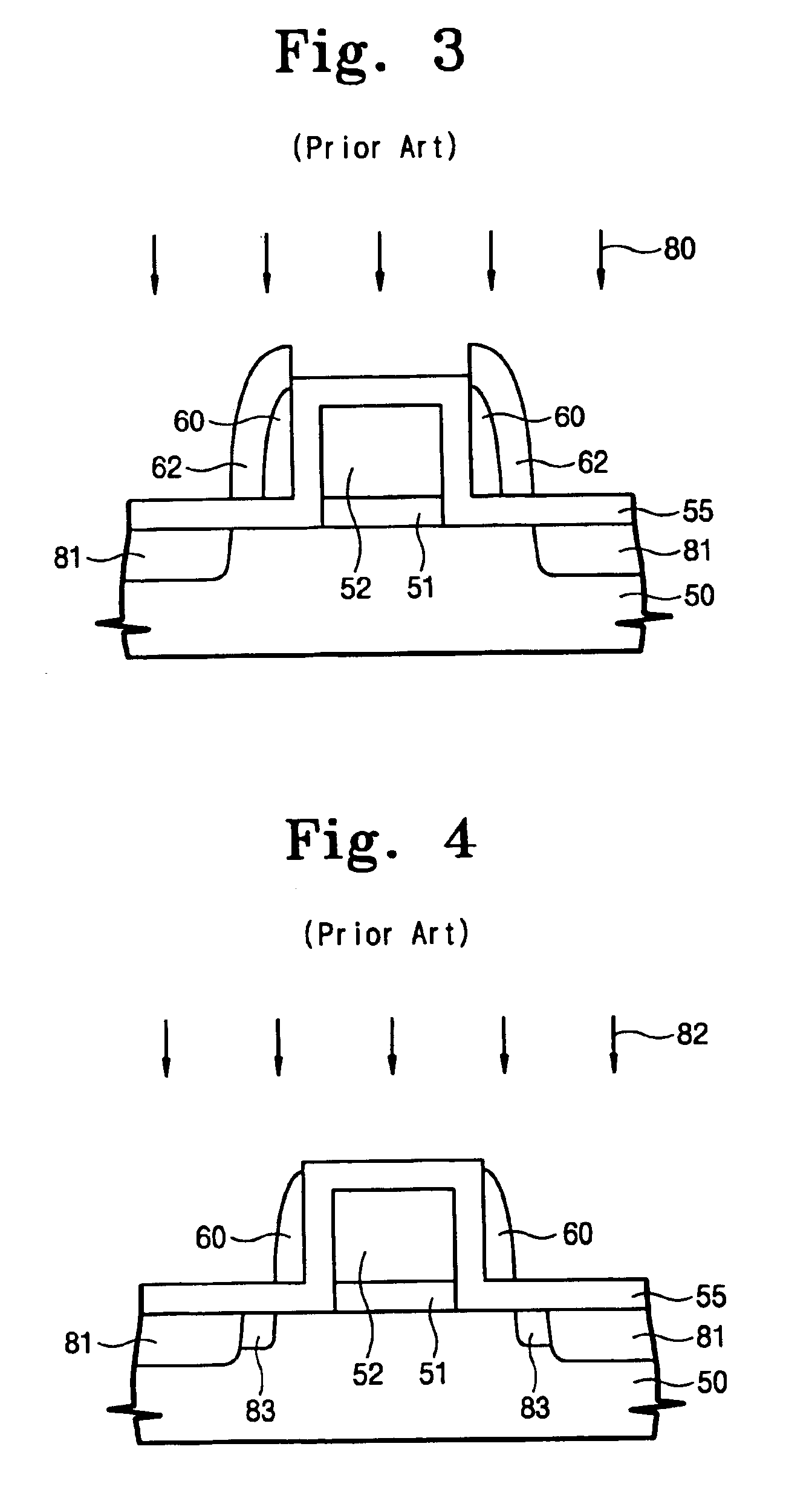
Unfortunately, the above-explained method is not efficient in that an ion implantation process must be carried out three times in order to form a medium-concentration junction area between a low- and a high-concentration junction area.

Method used


Image

  • Semiconductor transistor using L-shaped spacer
  • Semiconductor transistor using L-shaped spacer
  • Semiconductor transistor using L-shaped spacer

Examples


Embodiment Construction

[0032]Korean Patent Application No. 2001-31030, filed on Jun. 2, 2001, and entitled: “Semiconductor Transistor Using L-shaped Spacer and Method of Fabricating the Same,” is incorporated by reference herein in its entirety.

[0033]The present invention will now be described more fully hereinafter with reference to the accompanying drawings, in which preferred embodiments of the present invention are shown. The present invention may, however, be embodied in different forms and should not be construed as limited to the embodiments set forth herein. Rather, these embodiments are provided so that this disclosure will be thorough and complete, and will fully convey the scope of the invention to those of ordinary skill in the art. In the drawings, the thickness of layers and regions are exaggerated for clarity. It will also be understood that when a layer is referred to as being “on” another layer or substrate, it may be directly on the other layer or substrate, or intervening layers may als...


PUM


Abstract

The present invention provides a semiconductor transistor using an L-shaped spacer. The semiconductor transistor includes a gate pattern formed on a semiconductor substrate and an L-shaped third spacer formed beside the gate pattern and having a horizontal protruding portion. An L-shaped fourth spacer is formed between the third spacer and the gate pattern, and between the third spacer and the substrate. A high-concentration junction area is positioned in the substrate beyond the third spacer, and a low-concentration junction area is positioned under the horizontal protruding portion of the third spacer. A medium-concentration junction area is positioned between the high- and low-concentration junction areas.

Description

[0001]This application is a division of application Ser. No. 10 / 103,759, filed Mar. 25, 2002, now U.S. Pat. No. 6,693,013.BACKGROUND OF THE INVENTION[0002]1. Field of the Invention[0003]The present invention generally relates to a semiconductor device. More specifically, the present invention is directed to a semiconductor transistor using an L-shaped spacer.[0004]2. Description of the Related Art[0005]As semiconductor devices become more highly integrated, there is an increased demand for a method of suppressing a short channel effect. To this end, a commonly used structure is a lightly doped drain (LDD) structure where a low-concentration junction area is located on a lateral surface of a high-concentration junction area in a drain.[0006]FIG. 1 and FIG. 2 are sectional diagrams for explaining a method of forming a conventional semiconductor transistor.[0007]Referring now to FIG. 1, a gate oxide layer pattern 11 and a gate conductive layer pattern 12 are sequentially formed on a se...

Claims


Application Information

Patent Timeline
IPC IPC(8): H01L21/336H01L21/02H01L29/78
CPCH01L29/66507H01L29/66515H01L29/6653H01L29/6656H01L29/6659H01L29/66598H01L29/78
Inventor BAE, GEUM-JONGLEE, NAE-INRHEE, HWA-SUNGKO, YOUNG-GUNCHOE, TAE-HEEKIM, SANG-SU
Owner SAMSUNG ELECTRONICS CO LTD
Learn More