Double time-constant for electrostatic discharge clamping

a technology of electrostatic discharge and clamping, applied in the field of multiple time constant circuits, can solve the problems of small currents that require a substantial amount of time to charge up the first node, damage to certain portions of the device, and different problems of electronic devices, etc., to achieve the effect of increasing the voltage level and the requirement of voltage level

Inactive Publication Date: 2005-07-12
MICROSEMI SEMICON U S
View PDF1 Cites 9 Cited by
  • Summary
  • Abstract
  • Description
  • Claims
  • Application Information

AI Technical Summary

Problems solved by technology

One problem associated with handling and operating electronic devices, such as integrated circuit chips, includes protecting the devices from electrostatic discharge (ESD).
Electrostatic discharges may cause various problems on electronic devices.
For example, a large electrostatic may cause a sufficient energy spike in various circuitry of the electronic device such that damage to certain portions of the device may occur.
Therefore, that small current will require a substantial amount of time to charge up the first node 155.
One problem associated with the implementation shown in FIG. 1 is that the clamping function may be inadvertently triggered by a normal power-on event that has a fast rise time but does not exceed normal operation voltages.
Among the problems associated with triggering an ESD clamp upon a power up sequence includes interferences with power-on sequences, a possible reduction in the reliability of the ESD clamps, and / or occurrence of unintended device behavior, such as device latch-up due to large clamp currents.
Another problem associated with the implementation shown in FIG. 1 is that the deactivation of the clamping function may occur (i.e., turning the clamping circuit 100 clamping function off) before a desirable time because the ESD event may not be completely extinguished before the clamping function is deactivated.
Therefore, the electronic device hosting the circuit 100 may become damaged.

Method used


Image

  • Double time-constant for electrostatic discharge clamping
  • Double time-constant for electrostatic discharge clamping
  • Double time-constant for electrostatic discharge clamping

Examples


Embodiment Construction

[0022]Illustrative embodiments of the invention are described below. In the interest of clarity, not all features of an actual implementation are described in this specification. It will of course be appreciated that in the development of any such actual embodiment, numerous implementation-specific decisions must be made to achieve the developers' specific goals, such as compliance with system-related and business-related constraints, which will vary from one implementation to another. Moreover, it will be appreciated that such a development effort might be complex and time-consuming, but would nevertheless be a routine undertaking for those of ordinary skill in the art having the benefit of this disclosure.

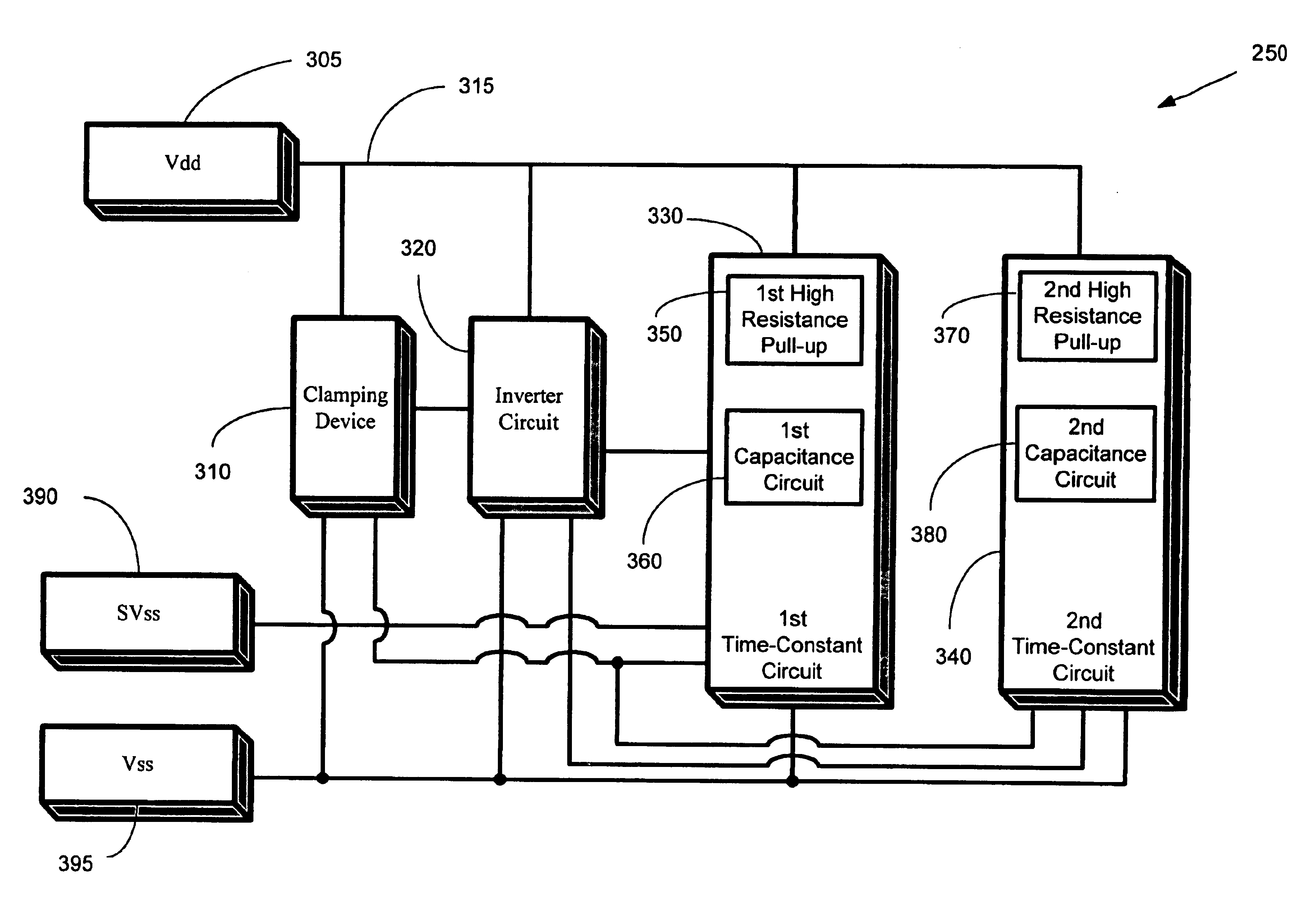
[0023]Embodiments of the present invention provide for an electrostatic discharge method and apparatus for providing a plurality of time-constants for implementing protection from electrostatic discharge (ESD) events. ESD events may include, but are not limited to, exposure to el...


PUM


Abstract

A method and apparatus is provided for clamping of an electrostatic discharge using multiple time-constants. A rise in a voltage level is detected. A first time-constant is provided to determine whether the rise in the voltage level is caused by an electrostatic event. A clamping function is provided to clamp the voltage level in response to a determination that the rise in the voltage level is caused by the electrostatic event. A second time-constant is provided to provide a time period for maintaining the clamping function for a period of time to substantially extinguish the electrostatic event.

Description

BACKGROUND OF THE INVENTION[0001]1. Field of the Invention[0002]This invention relates generally to telecommunications, and, more particularly, to providing a multiple time-constant circuit for performing electrostatic discharge clamping.[0003]2. Description of the Related Art[0004]In communication systems, particularly telephony such as a Plain Old Telephone System (POTS), it is common practice to transmit signals between a subscriber station and a central switching office via a two-wire, bi-directional communication channel. A line card generally connects the subscriber station to the central switching office. The functions of the line card include supplying talk battery, performing wake-up sequences of circuits to allow communications to take place, and the like. Voltage signals are processed and conditioned when being driven onto telecommunication lines. These communication systems employ various electronic devices. Today's state of the art electronics provide for various circui...

Claims


Application Information

Patent Timeline
Patent Type & Authority Patents(United States)
IPC IPC(8): H02H9/04H02H1/00H02H1/04
CPCH02H9/046H02H1/04
Inventor BLUMENTHAL, JEFFREY M.
Owner MICROSEMI SEMICON U S
Why Eureka
Try Eureka