Driving assist system for vehicle

a technology for driving assistance and vehicles, applied in the direction of process and machine control, pedestrian/occupant safety arrangement, instruments, etc., can solve the problems of difficulty in maintaining a suitable vehicle distance and difficulty in alleviating mental stress on the operator

Inactive Publication Date: 2005-07-12
NISSAN MOTOR CO LTD
View PDF32 Cites 22 Cited by
  • Summary
  • Abstract
  • Description
  • Claims
  • Application Information

AI Technical Summary

Benefits of technology

[0006]The present invention is to provide a driving assist system for a vehicle, a method therefor and a vehicle equipped with this system which, along with performing the vehicle distance control, assists the driving operation by an operator by varying the accelerator pedal reaction force according to change of the vehicle traveling situation.

Problems solved by technology

However, with the above described system, there is a possibility that it may become difficult to maintain a suitable vehicle distance, due to control delays in the system upon deceleration of the vehicle in front and a cut-in vehicle (a vehicle that has just cut in in front of the subject vehicle) from an adjacent vehicle lane or the like.
Accordingly, although it is possible to alleviate the physical load upon the operator by performing the vehicle distance control, it has been difficult to alleviate the mental stress upon the operator.

Method used


Image

  • Driving assist system for vehicle
  • Driving assist system for vehicle
  • Driving assist system for vehicle

Examples


first embodiment -

[0028]-First Embodiment-

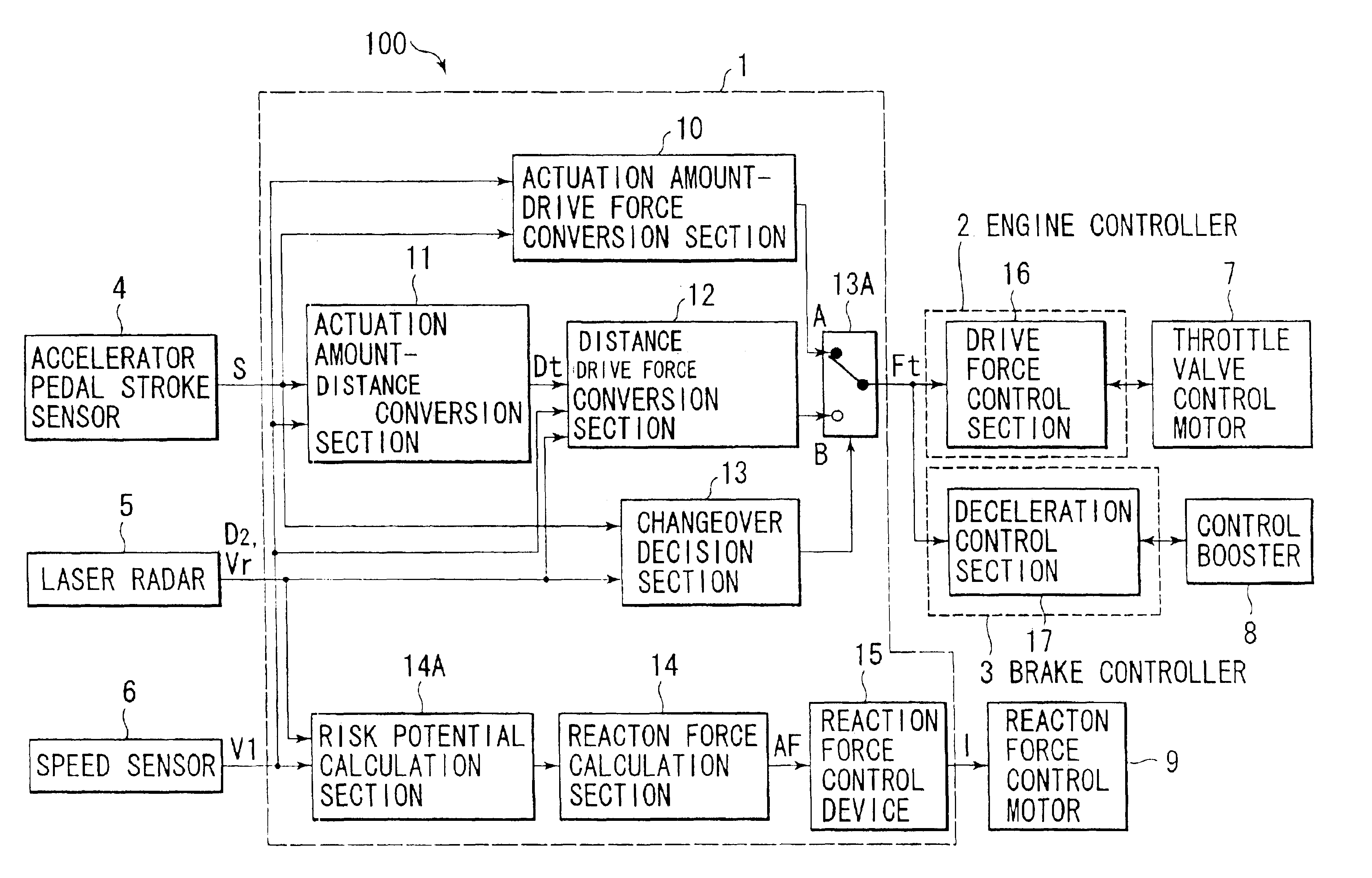
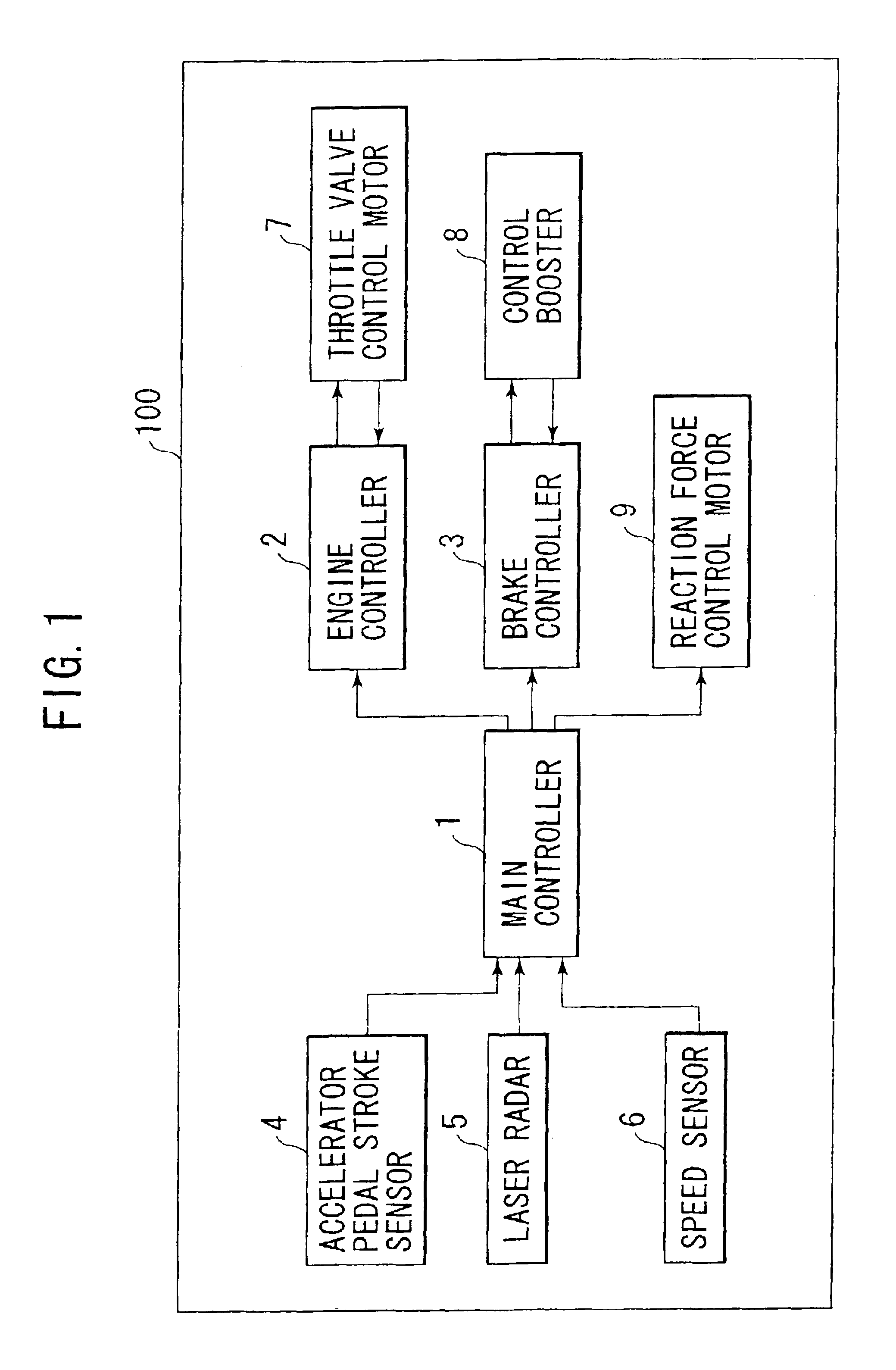
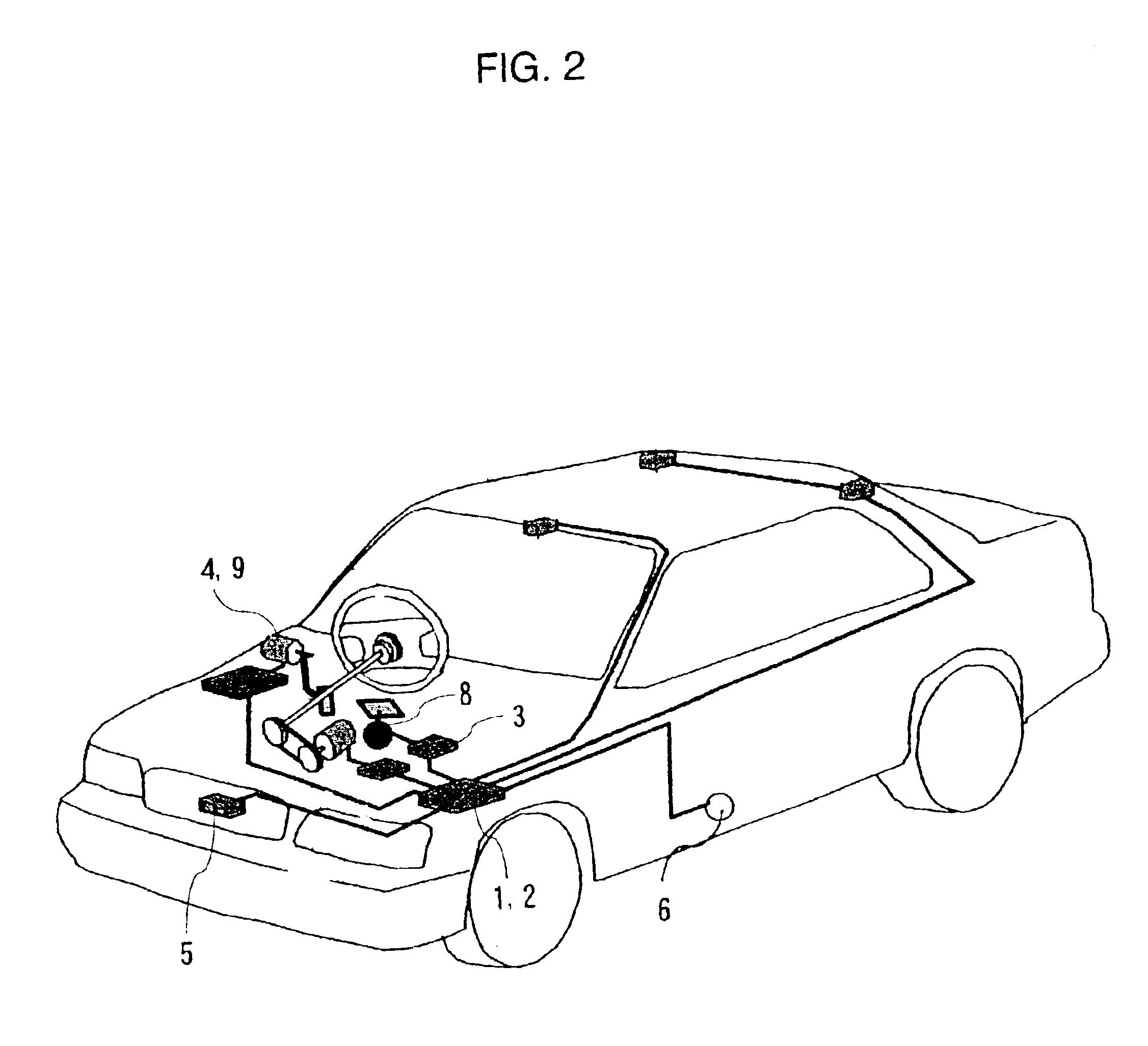
[0029]The first preferred embodiment of the driving assist system for a vehicle according to the present invention will now be explained with reference to the figures. FIG. 1 is a block diagram showing the structure of a driving assist system 100 for a vehicle according to this first preferred embodiment of the present invention, and FIG. 2 is a structural diagram of a vehicle to which this driving assist system 100 is fitted. Moreover, FIG. 3 is a figure showing the structure in the neighborhood of an accelerator pedal, while FIG. 4 is a figure showing the structure in the neighborhood of a throttle valve.

[0030]First, the structure of this vehicle driving assist system 100 will be explained.

[0031]As shown in FIG. 3, an accelerator pedal stroke sensor 4 is assembled to a reaction force control motor 9 which is disposed at the center of rotation of an accelerator pedal 19. The accelerator pedal stroke sensor 4 detects the amount of actuation of the accelerator...

second embodiment

[0088]-Second Embodiment-

[0089]In the following, the vehicle driving assist system according to the second preferred embodiment of the present invention will be explained with reference to the figures. FIG. 12 is a figure showing the structure of the vehicle driving assist system 200 according to this second preferred embodiment of the present invention. It should be understood that, in FIG. 12, elements which have the same functions as ones shown in FIG. 5 are designated by the same reference numerals. Here, explanations will focus upon the points in which this second preferred embodiment differs from the first preferred embodiment described above.

[0090]This vehicle driving assist system 200 according to this second preferred embodiment controls the drive force of the subject vehicle so that the vehicle speed V1 comes to be substantially equal to the target vehicle speed Vt which corresponds to the accelerator pedal actuation amount S. As shown in FIG. 12, the main controller 1A pe...

third embodiment -

[0115]-Third Embodiment-

[0116]In the following, the driving assist system for a vehicle according to the third preferred embodiment of the present invention will be explained. The structure of the vehicle driving assist system according to this third preferred embodiment is the same as that of the first preferred embodiment shown in FIG. 5. Here, explanations will focus upon the points in which this third preferred embodiment differs from the first preferred embodiment described above.

[0117]With this third preferred embodiment, the definition of the risk potential PF is varied between the vehicle distance control and the other type of control, i.e. drive force control. In the following, the setting of the risk potential PF for each type of control will be explained.

[0118]When no vehicle after which the subject vehicle should follow is present in front of the subject vehicle in its own vehicle lane, so that the drive force control is being performed according to the accelerator pedal...


PUM


Abstract

A vehicle driving assist system comprises a traveling situation detection device that detects a vehicle condition and a traveling environment around a subject vehicle; a risk potential calculation device that calculates a risk potential around the subject vehicle based upon detection results of the traveling situation detection device; an accelerator pedal reaction force control device that controls an actuation reaction force which is generated for an accelerator pedal based upon the risk potential which has been calculated by the risk potential calculation device; an actuation amount detection device that detects an actuation amount of the accelerator pedal; and a vehicle distance control device that controls a distance between the subject vehicle and a preceding vehicle present in front of the subject vehicle based upon the accelerator pedal actuation amount which is detected by the actuation amount detection device.

Description

BACKGROUND OF THE INVENTION[0001]1. Field of the Invention[0002]The present invention relates to a driving assist system for a vehicle that assists an operator to drive a vehicle, to a method therefor, and to a vehicle that is equipped with this system.[0003]2. Description of Related Art[0004]As a system for assisting an operator to drive a vehicle, there is known, the one disclosed in Japanese Patent Laid Open Publication No. 2000-54860. This system is one which, for automatic cruise control, varies the actuation reaction force of the accelerator pedal based upon the vehicle distance between the vehicle in front and the subject vehicle as detected by a laser radar system or the like. For example, with this system, during automatic cruise control, the accelerator pedal reaction force is set to be hard so as to allow the operator to rest his foot upon the accelerator pedal.SUMMARY OF THE INVENTION[0005]However, with the above described system, there is a possibility that it may becom...

Claims


Application Information

Patent Timeline
Patent Type & Authority Patents(United States)
IPC IPC(8): B60K31/00B60K26/02B60K26/00B60R21/00B60W10/04B60W10/06B60W10/18B60W10/184B60W30/00B60W30/16B60W50/14B60W50/16F02D11/04F02D29/02G08G1/16
CPCB60K31/0008B60W30/16B60K31/18B60K26/021B60W2750/308B60W2540/10B60W2754/30
Inventor EGAMI, MASAHIRO
Owner NISSAN MOTOR CO LTD
Why Eureka
Try Eureka