Disc drive head driver

a disc drive and head drive technology, applied in the field of disc drive head drives, can solve the problems of reducing the reliability of optical disc drives, causing backlash, and misalignment of racks, and achieve the effect of keeping the spacing between the rack and the rotation axis of the pinion constan

Inactive Publication Date: 2005-07-12
RAKUTEN GRP INC
View PDF8 Cites 7 Cited by
  • Summary
  • Abstract
  • Description
  • Claims
  • Application Information

AI Technical Summary

Benefits of technology

[0012]The head driver according to the present invention operates as follows when the rack extension direction is at a slant with the head movement direction. When the recording head moves, the swing arm that acts as the axis spacing retaining means swings, following the slant of the rack. Then, the rotation axis of the pinion supported by the swing arm moves. Therefore, the spacing between the rack and rotation axis of the pinion is kept constant. On the other hand, because the axis spacing retaining means is made of rigid material, there is no need for one of the pinion and the rack to be pressed against the other by the spring force. Therefore, no excess power is applied to the gear-mating surface of the rack and the pinion. This ensures proper engagement between the rack and the pinion. The recording head can move speedily and smoothly.

Problems solved by technology

This implies that a size error, if introduced during hole and / or boss manufacturing, would sometimes result in the rack 6 being misaligned with the sliding direction of the optical head 1.
This condition sometimes results in an abnormal sound being generated, the feeding load of the optical head being varied, and the optical head positioning precision being degraded, thus decreasing the reliability of the optical disc drive.
As a result, the technology solves the problems described above; that is, it prevents the pinion from not rotating properly and a backlash from being generated between the pinion and the rack.
This generates a problem in the smooth movement of the optical head when it moves at a high speed.
However, an attempt to do so exerts a force on the mating surface between the pinion and the rack, and the force prevents the pinion from properly engaging with the rack.
However, this technology requires the spring force strong enough for engaging the pinion with the rack even if the optical head is moved by the maximum output of the motor.
However, even in this case, the spring force ensuring the engagement between the pinion and the rack is required.
However, according to the technology disclosed in the publications described above, the spring force increases the force of engagement between the pinion and the rack.
This presents a problem in high-speed, smooth movement of the optical head.

Method used


Image

  • Disc drive head driver
  • Disc drive head driver
  • Disc drive head driver

Examples


Embodiment Construction

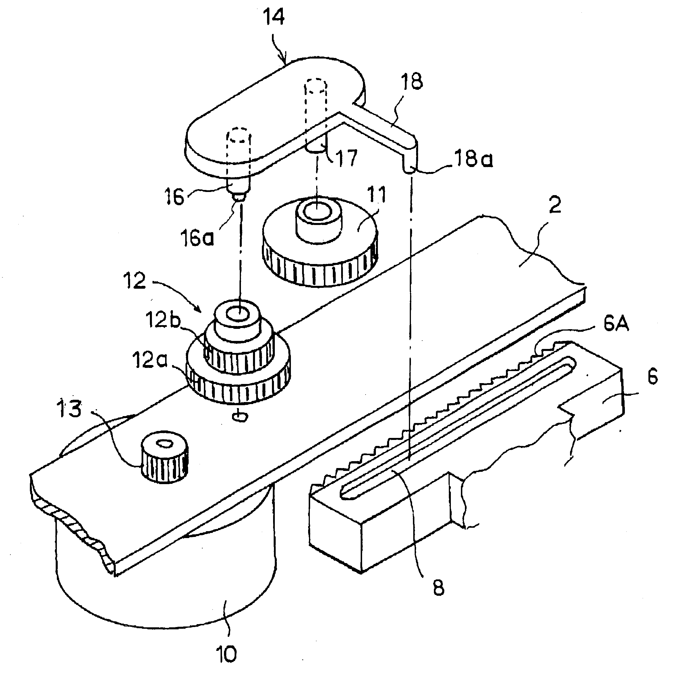
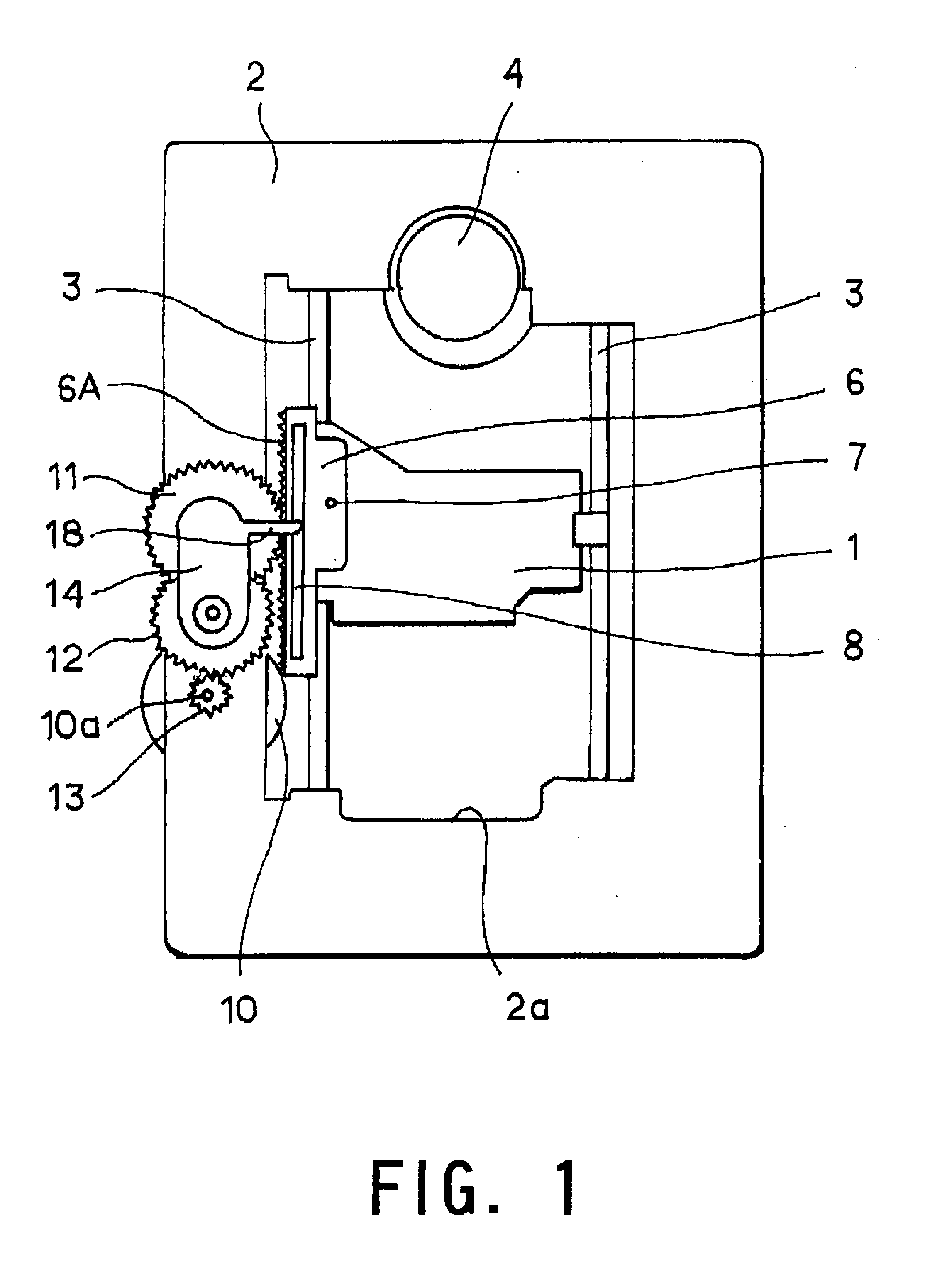
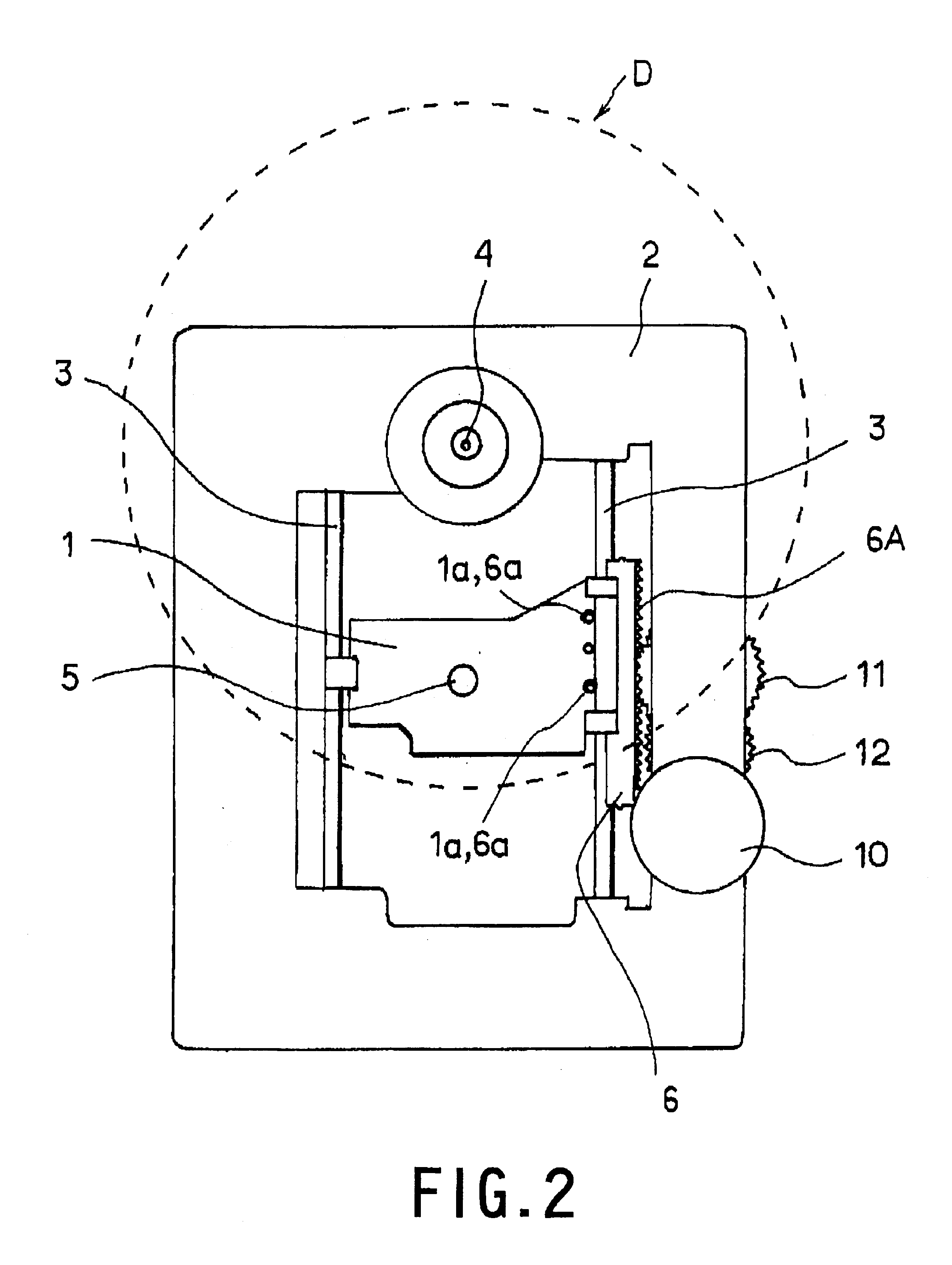
[0025]Next, an embodiment of the present invention will be described with reference to the drawings. FIG. 1 is a front view of an optical head driver in an embodiment in which the present invention is applied to an optical disc drive, and FIG. 2 is a rear view of the optical head driver. FIG. 3 is an enlarged front view of the major components, and FIG. 4 is a cross section view taken on line AA in FIG. 3. Referring to those figures, a chassis 2 that looks like a rectangular board has a head movement window 2a. In this head movement window 2a is provided a pair of parallel guide rails 3, 3 supported by the chassis 2. An optical head 1 is slidably supported on the guide rails 3, 3. Also provided on the chassis 2 is a spindle motor 4. This motor rotates an optical disc D, indicated by a dotted line in the figure, at a high speed. The guide rails 3, 3 extend over an optical disc D in its radial direction. Therefore, the optical head 1 is slidably supported such that it moves back and f...


PUM

PropertyMeasurementUnit
rotation forceaaaaaaaaaa
speedaaaaaaaaaa
areaaaaaaaaaaa

Abstract

The present invention eliminates variations in the engagement between a rack and a pinion, which drive a recording head, to enable the head to move speedily and smoothly. A head driver includes a rack provided on a recording head that slidingly moves over a recording disc and a pinion engaged with the rack and rotated by a drive motor, wherein there are provided a concave groove, provided on the rack and running in parallel with rack tooth, and a swing arm with which a rigid guide, guided by the concave groove, is integrated and on which a rotation axis of the pinion is provided. When the rack is at a slant with the movement direction, the swing arm swings, following the slant of the rack to keep constant the spacing between the rack and the pinion.

Description

BACKGROUND OF THE INVENTION[0001]1. Field of the Invention[0002]The present invention relates to a disc recording unit and more particularly to a disc drive that reads or writes information to or from a recording disc such as a CD or DVD. Still more particularly, the present invention relates to a head driver that moves the recording head over a recording disc.[0003]2. Description of the Background Art[0004]Recently, there is much effort being made to develop an optical disc drive as a disc recording drive. Among other things, an optical disc drive is required to write data at a high speed. A driver, which radially moves an optical head for recoding information signals on an optical disc, is also required to feed the head precisely. An optical head driver with the rack-and-pinion mechanism is proposed as an optical head driver satisfying this requirement. FIG. 11 is a front view showing the conceptual configuration of the driver. A chassis 2, has a spindle motor 4 thereon that rotat...

Claims


Application Information

Patent Timeline
Patent Type & Authority Patents(United States)
IPC IPC(8): G11B7/085F16H19/04G11B21/02
CPCG11B7/08582
Inventor SUDOU, SHINICHI
Owner RAKUTEN GRP INC
Why Eureka
Try Eureka