Suction brush assembly having rotation roller for sweeping dust

a technology of rotating rollers and suction brushes, which is applied in the field of vacuum cleaners, can solve the problems of dust on the fabrics getting off from the fabrics, difficult brush application, and protrusions hitting the fabrics, and achieves the effect of cleaning the fabrics more efficiently and removing the dust on the fabrics

Inactive Publication Date: 2005-07-19
SAMSUNG GWANGJU ELECTRONICS CO LTD
View PDF25 Cites 42 Cited by
  • Summary
  • Abstract
  • Description
  • Claims
  • Application Information

AI Technical Summary

Benefits of technology

[0009]The present invention has been made to overcome the above-mentioned problems of the prior art. Accordingly, it is an object of the present invention to provide a suction assembly of a vacuum cleaner enabling a user to clean fabrics more efficiently as the effect of removing dust on the fabrics increases.
[0016]According to the present invention, when the user wants to clean fabrics such as bedclothes or a carpet, the effect of hitting is firmly secured, thus the effect of removing dust remarkably increases.

Problems solved by technology

Generally, the above brush 20 is used when the user cleans the floor, but sometimes there is a difficulty in applying the brush 20 depending on the condition of the surface.
Therefore, when the rotation roller is rotated, the protrusions hit the fabrics.
This results in the dust on the fabrics getting off from the fabrics, and the fallen dust being drawn through the brush.
However, since the rotation roller is simply rotated by the friction force with the fabrics in the conventional brush for fabrics, there is a problem in that the rotation roller cannot be easily rotated.
In that case, the cleaning efficiency can be weak or even non-existent.
Accordingly, all of the protrusions hit the fabrics, resulting in a weakened hitting efficiency.

Method used


Image

  • Suction brush assembly having rotation roller for sweeping dust
  • Suction brush assembly having rotation roller for sweeping dust
  • Suction brush assembly having rotation roller for sweeping dust

Examples


Embodiment Construction

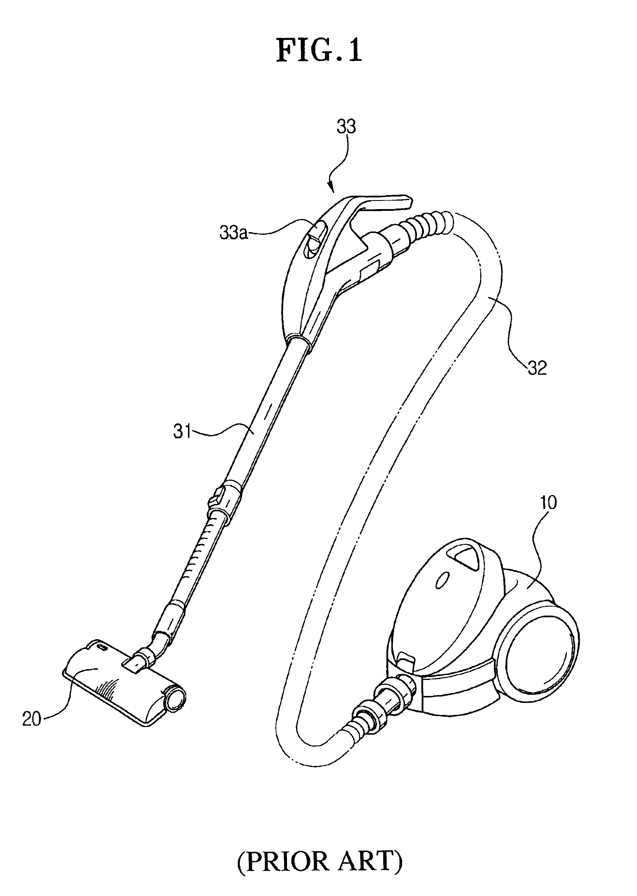
[0022]Hereinbelow, the preferred embodiment of the present invention will be described in greater detail by referring to the appended drawings. In the drawings, the same reference numbers represent the same or similar elements in the different drawings whenever possible. In the description of the present invention, the description of each part of a conventional vacuum cleaner as shown in FIG. 1 will be omitted.

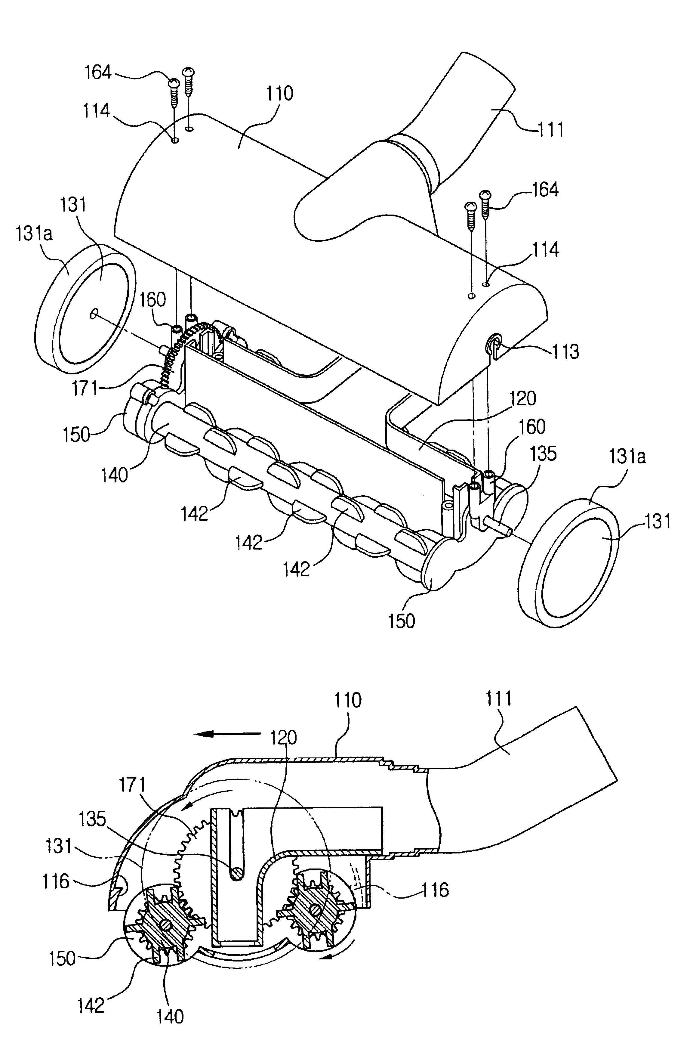
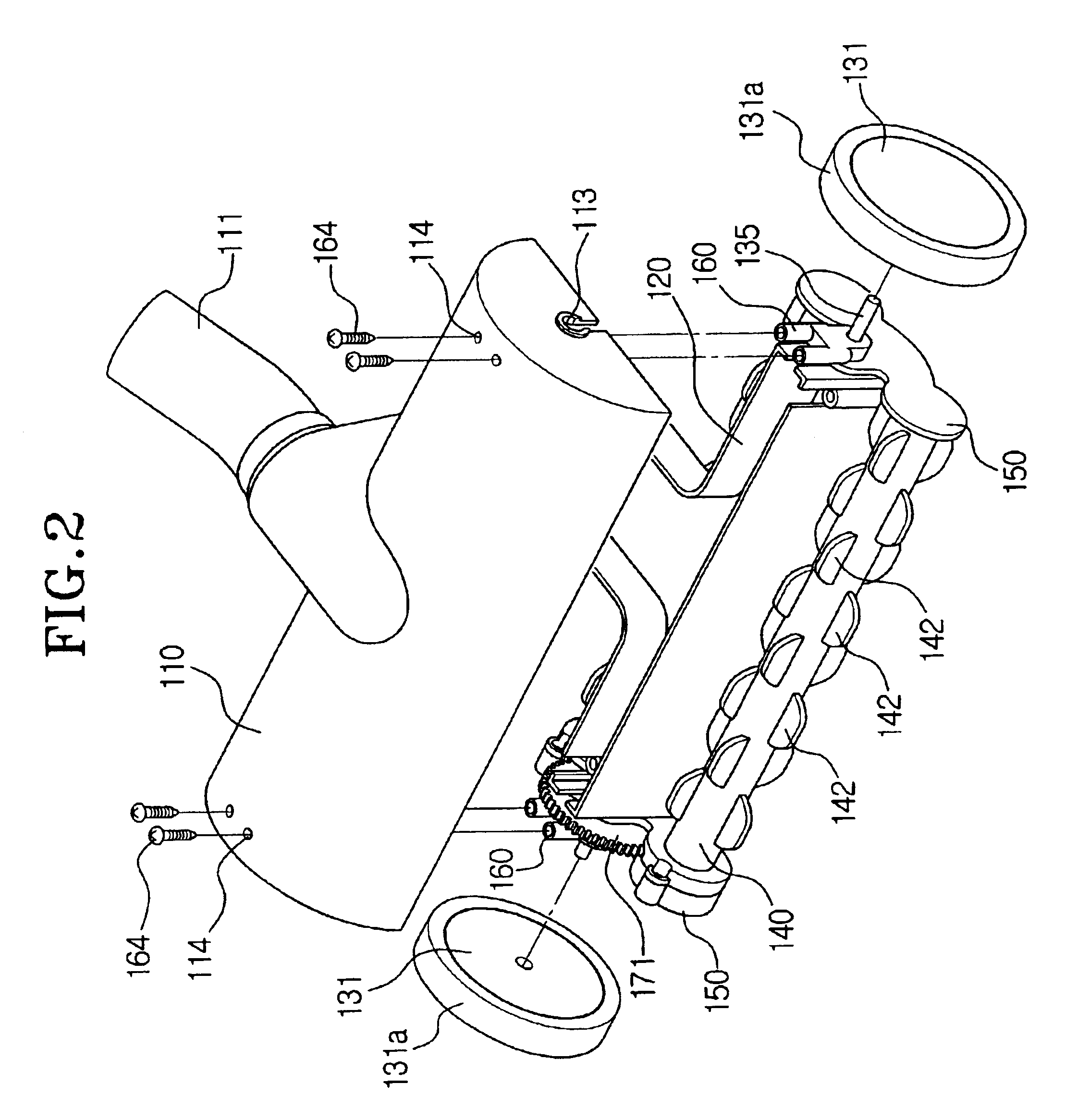
[0023]FIGS. 2 and 3 are exploded perspective views showing a suction brush assembly according to the present invention. The suction brush assembly has a housing 110 connected with an extension pipe (not shown) of the vacuum cleaner, a pair of rotation rollers 140 disposed at a lower part of the housing 110, and a pair of wheels 131 disposed at both sides of the housing 110.

[0024]The housing 110 has a connection pipe 111 connected with the extension pipe of the vacuum cleaner. A duct member 120 is installed at the lower part of the housing 110. The duct member 120 and the housi...


PUM


Abstract

A suction brush assembly of a vacuum cleaner has a housing having a suction duct to provide a suction passage for dust, a rotation roller having a plurality of ribs formed at an outer circumference, a wheel disposed at the housing, and a power transmission unit to rotate the rotation member by exerting a rotation force of the wheel to the rotation member when the wheel is rotated. The wheel and the rotation member are rotated in directions opposite to each other by the power transmission unit. When a user wants to clean fabrics such as bedclothes or a carpet, the effect of hitting of the ribs can be firmly secured due to the rotation of the rotation rollers. Therefore, the effect of removing dust remarkably increases.

Description

BACKGROUND OF THE INVENTION[0001]1. Field of the Invention[0002]The present invention relates to a vacuum cleaner, and more particularly, to a suction brush assembly having a rotation roller for sweeping dust from bedclothes and etc., and a vacuum cleaner having the same.[0003]2. Description of the Prior Art[0004]FIG. 1 is a view showing the appearance of a conventional vacuum cleaner. The conventional vacuum cleaner has a body 10 having a driving device such as a motor, a connection hose 32 connected with the body 10, a handle 33 disposed at the end of the connection hose 32, an extension pipe 31 disposed at the handle 33, and a brush 20 disposed at the end of the extension pipe 31. When a user drives the vacuum cleaner by manipulating a switch 33a disposed at the handle 33, the vacuum cleaner conducts a suction operation as the motor in the body 10 is driven. Accordingly, dust is drawn into the vacuum cleaner through a suction port formed at the bottom of the brush 20. The drawn d...

Claims


Application Information

Patent Timeline
Patent Type & Authority Patents(United States)
IPC IPC(8): A47L9/04A47L5/22A47L5/34A47L9/02
CPCA47L5/34A47L9/0411A47L9/0433A47L9/0488A47L9/0494A47L9/02
Inventor JOO, SUNG-TAEOH, JANG-KEUN
Owner SAMSUNG GWANGJU ELECTRONICS CO LTD
Why Eureka
Try Eureka