Fuel injection control device

a control device and fuel injection technology, applied in the direction of electrical control, process and machine control, instruments, etc., can solve the problems of difficult combustion, insufficient control of ignition timing, and control of the ignition period of fuel, and achieve the effect of improving the exhaust gas

Inactive Publication Date: 2005-07-19
ISUZU MOTORS LTD
View PDF12 Cites 7 Cited by
  • Summary
  • Abstract
  • Description
  • Claims
  • Application Information

AI Technical Summary

Benefits of technology

[0012]It is an object of the present invention to provide a fuel injection control device which al

Problems solved by technology

Thus, this early pre-mixing combustion (injection) is effective in improving the exhaust gas; however, control of the ignition period of the fuel is difficult, so that such combustion has been difficult to realize.
In other words, in the case of the ordinary combustion described above, since the f

Method used


Image

  • Fuel injection control device
  • Fuel injection control device
  • Fuel injection control device

Examples


Embodiment Construction

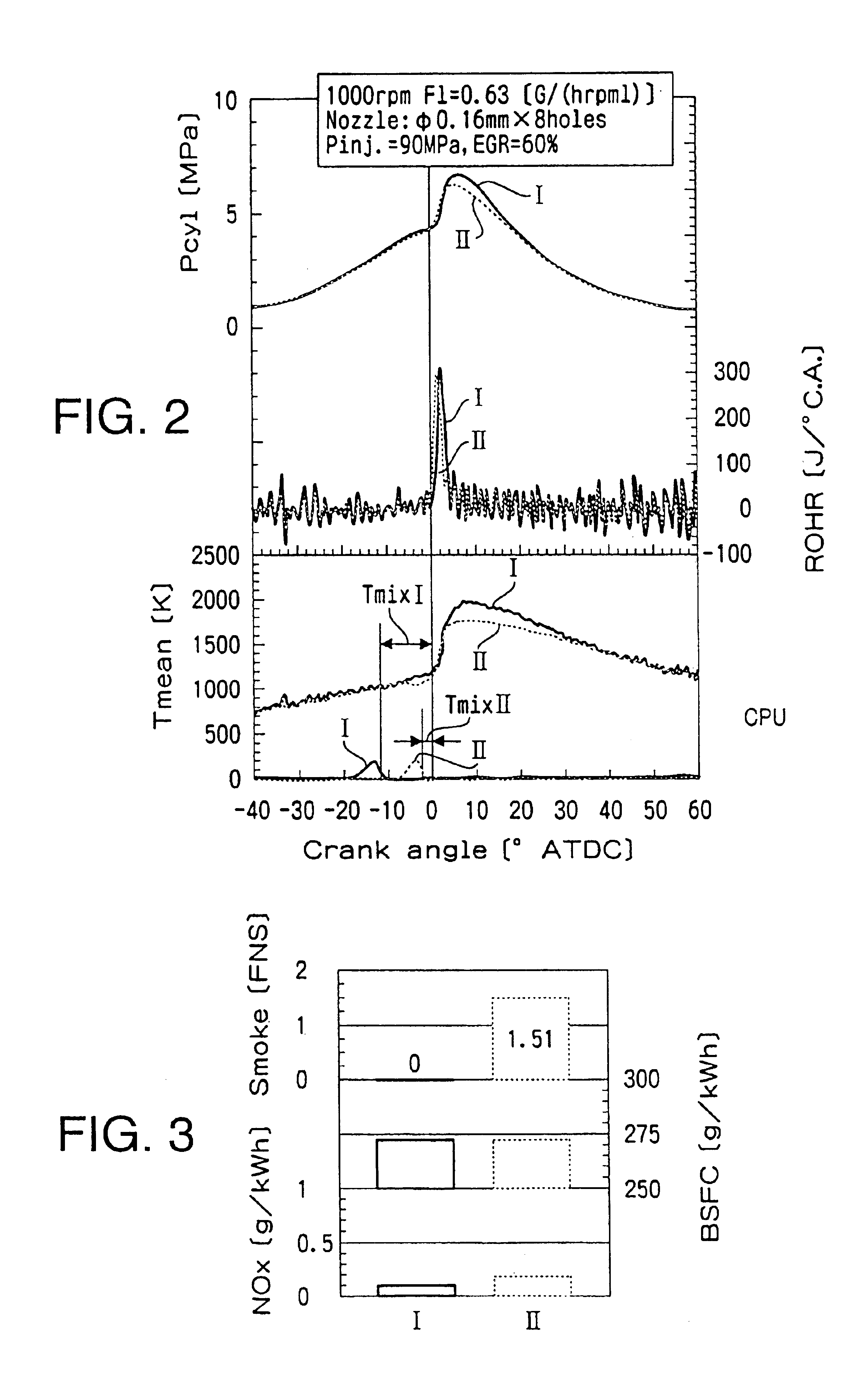
”, the present inventors discovered that in the case of early pre-mixing combustion, there is a danger not only of a failure to obtain an exhaust gas cleansing effect, but also of a deterioration in HC (Hydrocarbon) emission amounts, fuel consumption, unless the period extending from the time of completion of fuel injection to the beginning of ignition (this period is referred to as the “pre-mixing period” in the present specification) is controlled to an appropriate range.

[0011]In other words, appropriate control of the ignition timing and pre-mixing period of the fuel is important for realizing early pre-mixing combustion.

SUMMARY OF THE INVENTION

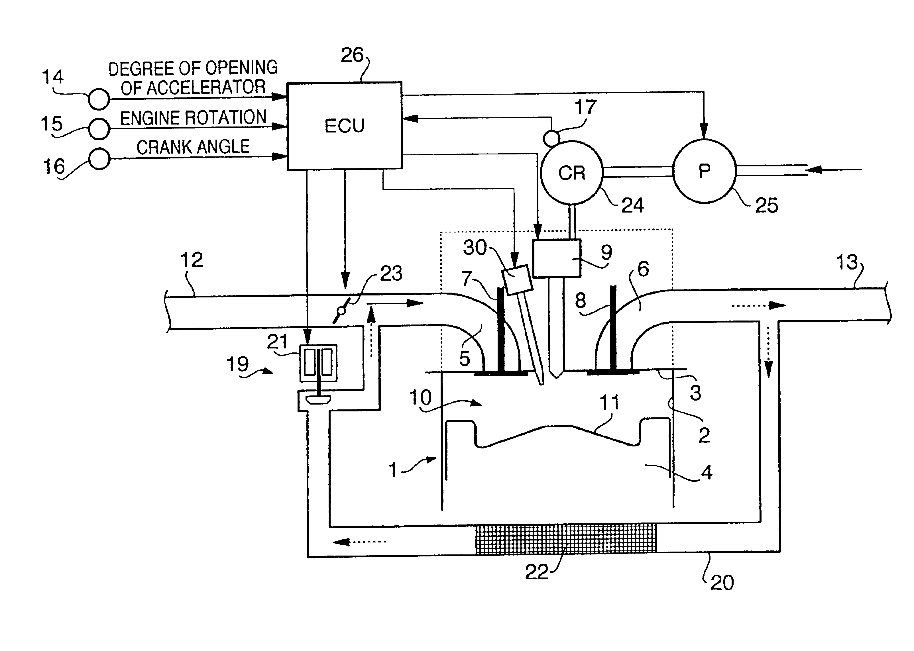
[0012]It is an object of the present invention to provide a fuel injection control device which allows an improvement of exhaust gas by appropriately controlling the pre-mixing period of the fuel.

[0013]In order to achieve the abovementioned object, the present invention is a fuel injection control device in which fuel injected into the com...


PUM


Abstract

A fuel injection control device in which fuel injected into the combustion chamber is ignited after a pre-mixing period has elapsed following the completion of the injection of the fuel, includes target pre-mixing period determining unit for determining the target pre-mixing period on the basis of the engine operating conditions, actual pre-mixing period detection unit for detecting the actual pre-mixing period, and pre-mixing period adjustment means for adjusting the pre-mixing period of the fuel so that the actual pre-mixing period approaches the target pre-mixing period. With this device, the pre-mixing period of the fuel can be appropriately controlled, and the exhaust gas can be reliably improved.

Description

CROSS REFERENCE TO RELATED APPLICATION[0001]Applicant hereby claims foreign priority benefits under U.S.C. § 119 of Japanese Patent Application No. 2003-122026, filed on Apr. 25, 2003, and the content of which is herein incorporated by reference.BACKGROUND OF THE INVENTION[0002]1. Field of the Invention[0003]The present invention relates to a fuel injection control device with improved exhaust gas.[0004]2. Description of the Related Art[0005]Conventionally, in diesel engines, it has been common to perform combustion with fuel injected in the vicinity of compression top dead center, where a high temperature and high pressure are attained inside the cylinder (inside the combustion chamber).[0006]The injected fuel is mixed with intake air to form a mixture, this mixture is ignited so that a flame is formed, and combustion is continued by supplying subsequent injected fuel to this flame. In this combustion system, ignition begins during the injection of the fuel; this will be referred t...

Claims


Application Information

Patent Timeline
IPC IPC(8): F02D41/14F02D35/02F02D13/02F02D41/40F02D41/30F02D15/00F02B23/02F02B1/12F02B3/00F02B23/06F02B1/00F02B3/06F02M25/07F02B47/04F02D15/04F02D19/12F02D21/08F02D45/00F02M37/00F02M43/04F02M47/00F02M51/00
CPCF02D13/0215F02D15/00F02D35/028F02D41/3035F02D41/403F02B1/12F02B3/06F02B23/0696F02B2275/14F02D35/021F02D41/3041F02D2041/001F02D2200/1012F02D2250/31F02M25/0713F02M25/0727Y02T10/44Y02T10/18Y02T10/123F02D35/023F02M26/10F02M26/23Y02T10/12Y02T10/40
Inventor SHIMAZAKI, NAOKI
Owner ISUZU MOTORS LTD
Why Eureka
Try Eureka