Method for fabricating wovens

a technology of fabric and thread, applied in the field of airbag fabrics, can solve the problems of affecting the permeability of the fabric and its visual appeal, affecting the appearance, and affecting the effect of the fabric, so as to reduce the risk of warp threads sticking to each other, reduce the set per beam, and reduce the effect of set per beam

Inactive Publication Date: 2005-07-19
GLOBAL SAFETY TEXTILES
View PDF20 Cites 20 Cited by
  • Summary
  • Abstract
  • Description
  • Claims
  • Application Information

AI Technical Summary

Benefits of technology

[0007]This object is achieved by a method as it reads from claim 1. Distributing warp thread band required as a whole for a fabric on at least two warp beams, permits making use of warp thread material sized substantially better than in conventional techniques. Now, in fabricating the warp to be implemented prior to the method in accordance with the invention the individual threads can also be totally sized for a double warp spacing because of the reduced set per beam as a whole. It is because of this reduced set per beam as a whole as made possible by the method in accordance with the invention that the risk of warp threads sticking to each other is minimized in thus practically eliminating both tack and nesting of the warp threads (broken capillaries due to inadequate sizing) drastically reducing rejects in weaving.
[0008]In addition to this, the method in accordance with the invention has further advantages, especially when, where multi-ply, for example two-ply fabrics are involved, each ply can be produced separately with a warp thread band of its own beam. This now makes it possible to equalize the tension over the full width of the fabric, comparable to that of single-ply fabrics in usual fabrication on the market. In other words, the method in accordance with the invention now makes it possible to attain the necessary very high woven quality in achieving practically the same technical properties in each ply. Apart from this, the technique as described in accordance with the invention minimizes differences in tension when a change is made from a single-ply P3 / 3 portion to a two-ply weave.
[0009]In one advantageous aspect of the method in accordance with the invention each warp beam is controlled for tension independently of the other, further enhancing uniformity of the fabric especially where two-ply wovens are concerned.
[0010]In another advantageous aspect of the method in accordance with the invention the warp beams receive differing warp thread materials. If such a fabric is intended, for example, for an automotive side air bag, the ply of the fabric facing the vehicle occupant (when fitted in the vehicle) can be selected to achieve a surface of the air bag which is gentle to the head of the vehicle occupant, whereas the other fabric ply facing the window may comprise a warp thread material which is particularly resistant to shattered glass or the like. This aspect of the invention now makes it possible to employ warp threads differing in quality and price status for the two plies. Thus, materials of a higher quality or particularly expedient (for instance by being finer) may be selected for the “head side”, whilst rough, cheaper materials can be put to use for the “window side”. This also makes for better cost-effectiveness in production. Depending on the particular requirements warp threads differing in strength, texture, elasticity, fineness or material finish can be selected for the two or more plies of warp threads. Just as conceivable is the use of elastic warp threads on one beam and non-elastic warp threads on the other beam. This approach offers a wealth of advantages.

Problems solved by technology

These loose threads are a disadvantage as to permeability of the fabric and its visual appeal.
These are of a disadvantage in that they prompt differences in the physical properties between the lower and upper fabric.
Apart from this, conventional techniques are also deficient for further reasons.
For instance, collecting the warp thread band on the beam results in disadvantages in warp production, since in sizing, because of the high thread assignment on the beam there is no assurance of each and every thread being fully sized.
Thus, lack of complete sizing results in enormous losses in quality because of the resulting faults such as capillary breaks, fluff nesting, thread breakage.
It may happen in sizing that because of the high thread assignment per beam, several threads may tack together over a lengthy warp distance, this too resulting in the cited losses in quality in later weaving.
Here too, because of the cramped space in the back shed the cited losses in weave and quality may arise despite sizing being theoretically an optimum.

Method used


Image

  • Method for fabricating wovens
  • Method for fabricating wovens

Examples


Embodiment Construction

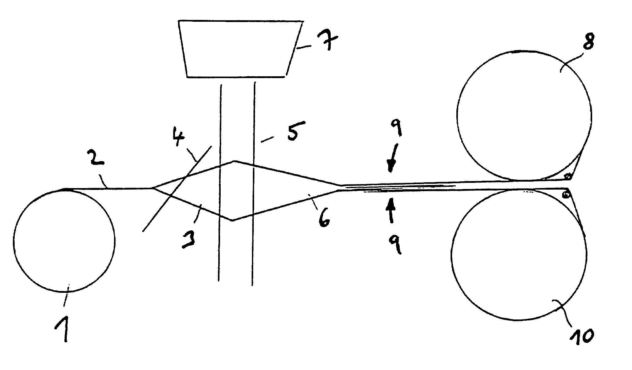
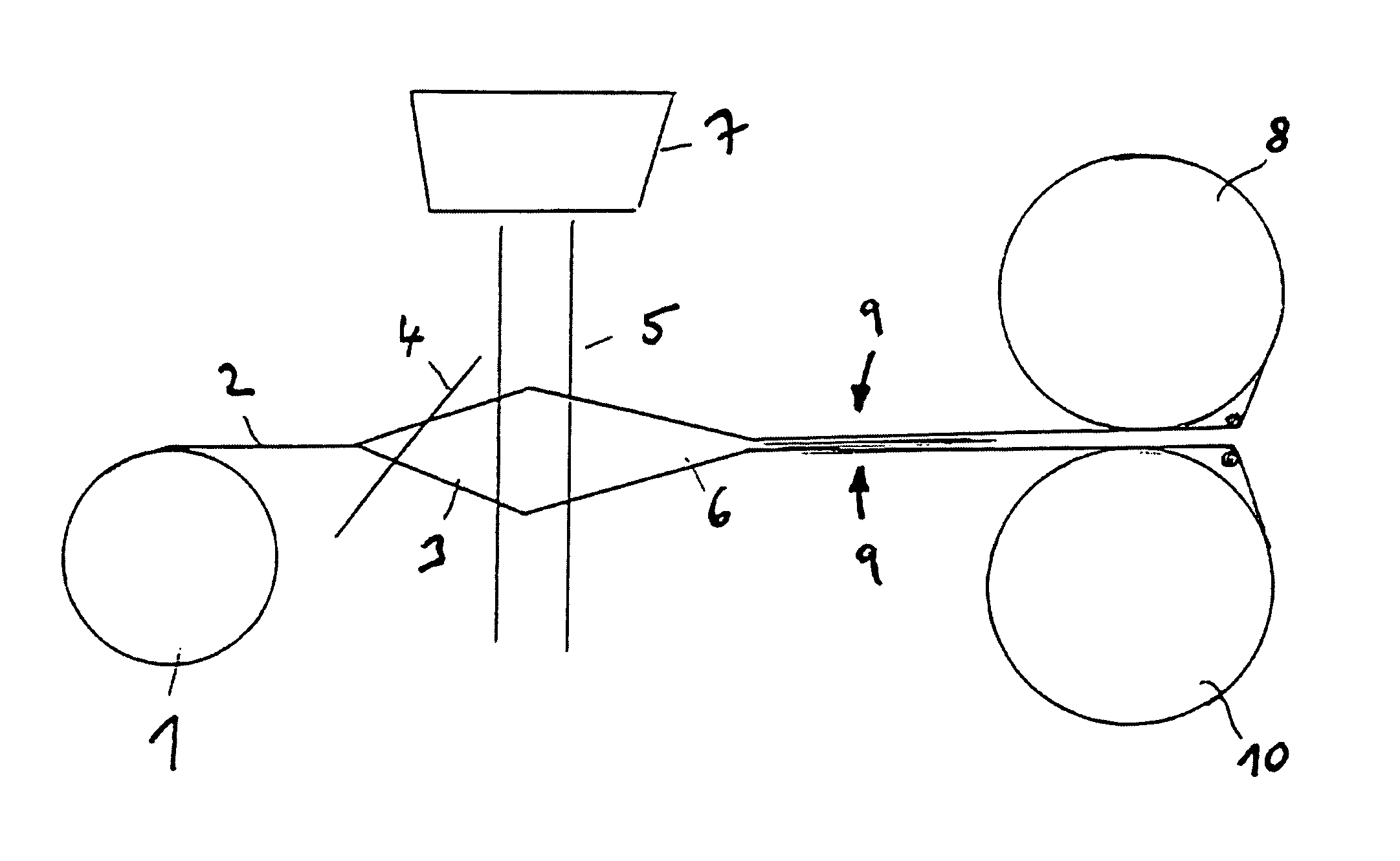
[0013]The method in accordance with the invention will now be detailed by way of example with reference to the drawing.

[0014]Referring now to the sole FIGURE of the drawing there is illustrated diagrammatically an arrangement of a weaving machine as viewed from the side. The warp beams 8 and 10 furnish bands 9 of warp threads to the weaving location. In the region of a harness packet 5 of a Jacquard machine 7 (indicated stylized) the reciprocating motion of the individual warp threads forms the back shed 6 and weave shed 3. In the region of the left-hand end of the shed 3 the reed 4 is evident, from which a single- and / or multi-ply fabric 2 is reeled by a product takeup reel 1.

[0015]Making use of two or more warp beams in accordance with the invention in interweaving single- and / or multi-ply fabrics also makes for a substantial cost advantage, since the frequency and time needed in changing the warp is reduced by the application of a plurality of warp beams.


PUM


Abstract

A method for weaving single-layered and/or multi-layered woven fabric, especially airbag fabric, includes interweaving warp threads delivered by at least two warp beams.

Description

CROSS-REFERENCE TO RELATED APPLICATIONS[0001]This application is a continuation of PCT / EP02 / 03630, filed Apr. 2, 2002 which claims priority to DE 101 15 891.2, filed Mar. 30, 2001, both of which are incorporated by reference herein.BACKGROUND AND SUMMARY OF THE INVENTION[0002]The invention relates to a method for weaving fabrics, more particularly air bag fabrics.[0003]In conventional fabric weaving techniques loose warp threads materialize from differences in having worked them in, following a change in weave. These loose threads are a disadvantage as to permeability of the fabric and its visual appeal. Known, in addition, are techniques for weaving two-ply fabrics from a warp band furnished by just a single warp beam in which due to the shed geometry differences in tension may materialize between the upper and lower fabric. These are of a disadvantage in that they prompt differences in the physical properties between the lower and upper fabric. These differences between the lower ...

Claims


Application Information

Patent Timeline
Patent Type & Authority Patents(United States)
IPC IPC(8): D03D39/16D03D39/00D03D1/02D03D11/02
CPCD03D1/02D03D11/02
Inventor BERGER, JOHANN
Owner GLOBAL SAFETY TEXTILES
Why Eureka
Try Eureka