Light source device for endoscope and assembly method for light source unit

Inactive Publication Date: 2005-07-19
ASAHI KOGAKU KOGYO KK
View PDF9 Cites 79 Cited by
  • Summary
  • Abstract
  • Description
  • Claims
  • Application Information

AI Technical Summary

Benefits of technology

[0006]An object of the present invention is to provide a light sou

Problems solved by technology

However, an LED is inferior in terms of t

Method used


Image

  • Light source device for endoscope and assembly method for light source unit
  • Light source device for endoscope and assembly method for light source unit
  • Light source device for endoscope and assembly method for light source unit

Examples


Example

[0020]The present invention is described below with reference to the embodiments shown in the drawings.

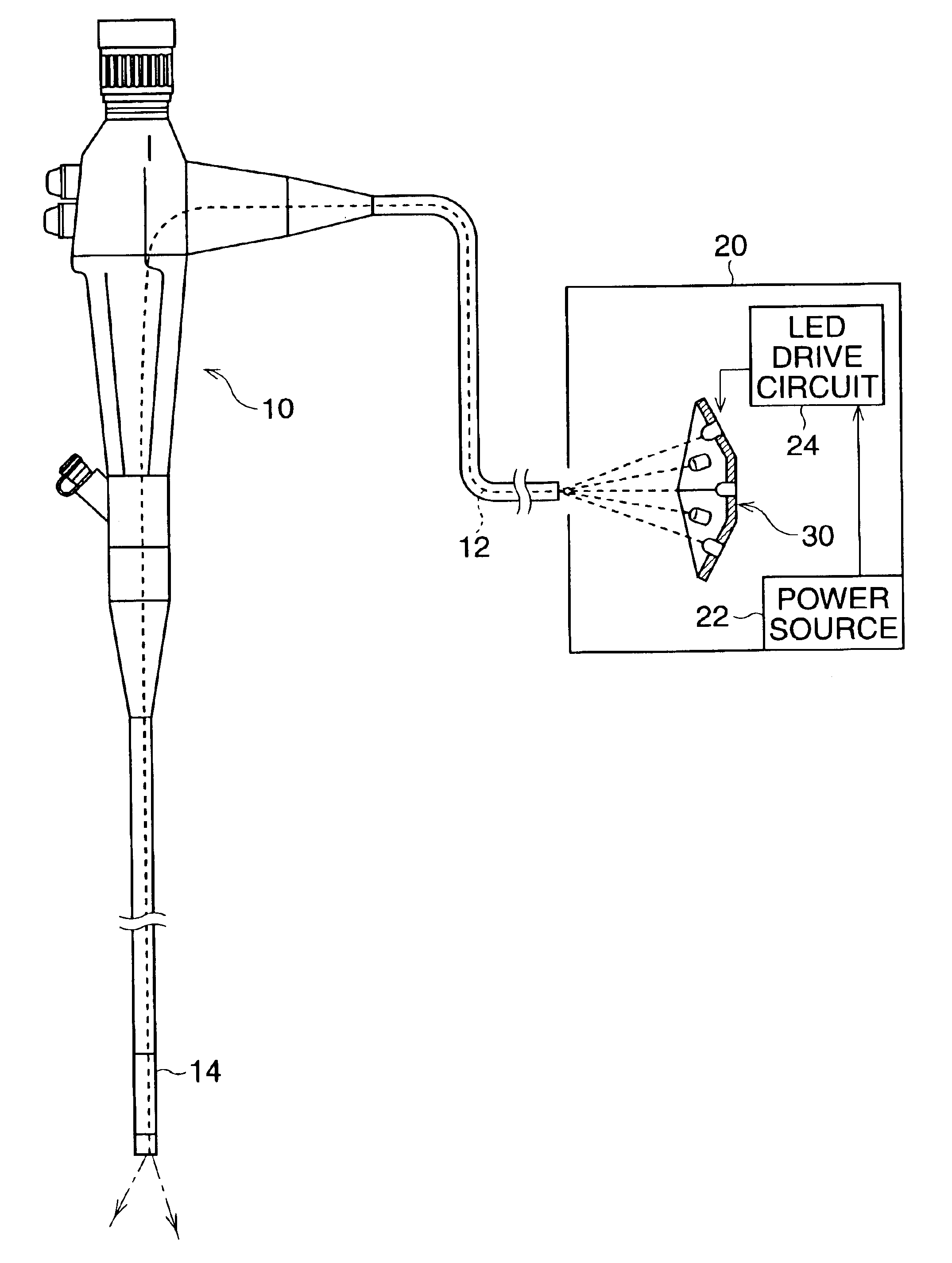
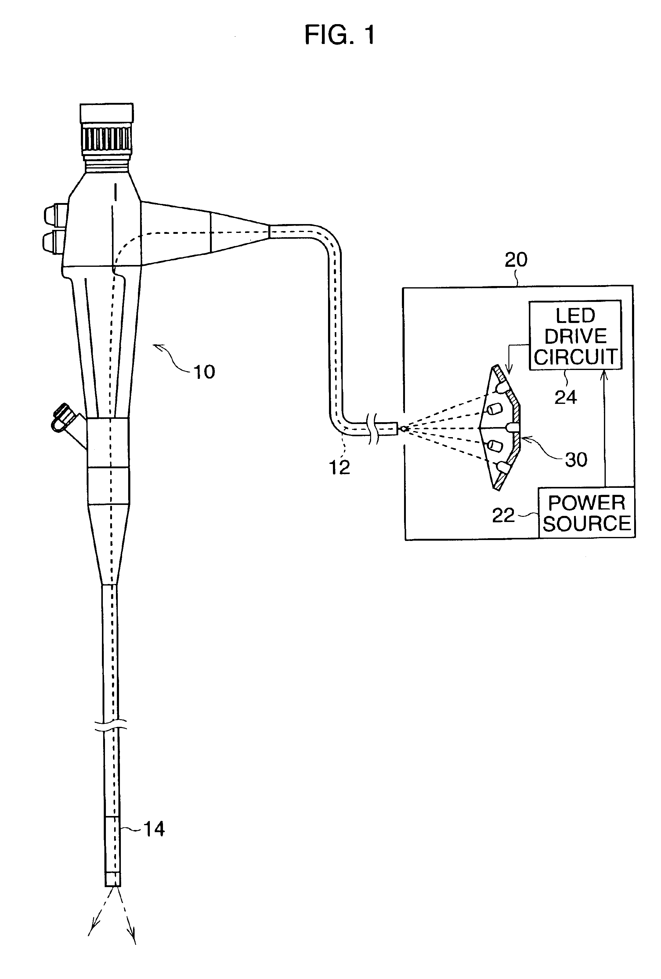
[0021]FIG. 1 illustrates a light source device of the present embodiment together with an endoscope. A light guide member 12 (indicated by a broken line in the figure) which is comprised of a plurality of glass fibers is inside the endoscope 10. One end of the light guide member 12 is optically connected to the light source unit 30 of the light source device 20, and the other end is positioned at the distal end of the insertion portion 14 of the endoscope. Note that, the light source unit 30 is arranged so that the center axis of the light source unit 30 coincides with the axis of the incident end face of the light guide member 12.

[0022]The light source device 20 comprises the light source unit 30 that includes a plurality of LED's which radiate white light, a power source 22 for supplying electric power to each LED, and an LED drive circuit 24 that controls the emission of each LE...


PUM


Abstract

A light source device for an endoscope is provided. The light source device comprises a light source unit that supplies illumination light to an incident end face of a light guide member, which is laid inside an endoscope. The light source unit comprises a plurality of reflecting board members. Each reflecting board member has at least one light emitting diode. The plurality of reflecting board members are assembled into a concaved open polyhedron, so that the light emitted from the light emitting diodes are concentrated onto the incident end face of the light guide member.

Description

BACKGROUND OF THE INVENTION[0001]1. Field of the Invention[0002]The present invention relates to a light source device for an endoscope.[0003]2. Description of the Related Art[0004]An endoscope comprises an insertion portion that is inserted into a digestive organ of a human body and the like. From the distal end of the insertion portion, illumination light is emitted. A light guide which is comprised of glass fibers is inside the endoscope. One end of the light guide is optically connected to a light source of an exclusive light source device. The other end of the light guide is positioned at the distal end of the insertion portion. Although a xenon lamp, a halogen lamp, and so forth are generally used for the light source, in recent years, light emitting diodes or LEDs may be utilized as the light source.[0005]An LED has superior characteristics, such as a miniature size, a small amount of wasted electricity, and little heat generation. However, an LED is inferior in terms of the ...

Claims


Application Information

Patent Timeline
IPC IPC(8): A61B1/06H05K1/18G02B23/26H01L33/60
CPCA61B1/0669H05K1/189A61B1/0684A61B1/07
Inventor OTA, NORIKOSATO, TAKASHI
Owner ASAHI KOGAKU KOGYO KK
Why Eureka
Try Eureka