Synthetic resin-made sliding bearing

a technology of synthetic resin and sliding bearing, which is applied in the direction of sliding contact bearings, shock absorbers, transportation and packaging, etc., can solve the problems of increasing the risk of sliding bearings, the working environment of sliding bearings between the mounting member of the vehicle body and the upper spring seat of the coil spring, and the inability to achieve the desired bearing function, etc., to achieve the effect of maintaining smooth steering force and avoiding sliding characteristics

Inactive Publication Date: 2005-07-19
OILES CORP
View PDF12 Cites 44 Cited by
  • Summary
  • Abstract
  • Description
  • Claims
  • Application Information

AI Technical Summary

Benefits of technology

[0007]According to the sliding bearing in accordance with the first aspect, since the second annular projection is disposed in the third annular groove defined by the pair of second annular suspended portions, it is possible to prevent the entry of dust, rainwater, muddy water, and the like onto the sliding surfaces of the radial sliding bearing piece from the inner peripheral side. Hence, it is possible to eliminate a decline of sliding characteristics attributable to the entry of the dust, rainwater, muddy water, and the like, thereby making it possible to maintain smooth steering force at the time of the steering operation for extended periods of time.
[0009]According to the sliding bearing in accordance with the second aspect, since the top surface of the first annular projection is higher than the top surface of the annular engaging projection, even if rainwater, muddy water, or the like has ridden over the annular engaging projection, the entry of such rainwater, muddy water, or the like onto the sliding surfaces of the thrust sliding bearing piece can be prevented by the first annular projection. This makes it possible to eliminate the decline of sliding characteristics attributable to the entry of the rainwater, muddy water, and the like, thereby making it possible to maintain smooth steering force at the time of the steering operation for extended periods of time.
[0011]According to the sliding bearing in accordance with the third aspect, since the lowering of the radial sliding bearing piece can be prevented by the annular step surface, the radial sliding bearing piece between the inner peripheral surface of the tubular portion and the outer peripheral surface of the hollow cylindrical portion can be held at a desired position.
[0013]According to the sliding bearing in accordance with the fourth aspect, since the top surface of the second annular projection is lower than the annular step surface, even if rainwater, muddy water, or the like has ridden over the second annular projection and entered between the inner peripheral surface of the tubular portion and the outer peripheral surface of the hollow cylindrical portion, the level of such rainwater, muddy water, or the like does not reach the annular step surface. Hence, it is possible to prevent the entry of such rainwater, muddy water, or the like onto the sliding surfaces of the thrust sliding bearing piece. This also makes it possible to eliminate the decline of sliding characteristics attributable to the entry of the rainwater, muddy water, and the like, thereby making it possible to maintain smooth steering force at the time of the steering operation for extended periods of time.
[0020]In accordance with the invention, it is possible to provide a synthetic resin-made sliding bearing which prevents the entry of dust, rainwater, muddy water, and the like onto sliding surfaces from the outer peripheral side and the inner peripheral side of the space where the sliding bearing piece is disposed, so as to eliminate a decline of sliding characteristics attributable to the entry of the dust, rainwater, muddy water, and the like, thereby making it possible to maintain smooth steering force at the time of the steering operation for extended periods of time.

Problems solved by technology

However, if dust, muddy water, or the like enters this space, there is a possibility that a desired bearing function cannot be obtained.
Meanwhile, since the strut-type suspension is fitted at a position where dust, rainwater, muddy water, or the like is directly applied during the traveling of the vehicle, the working environment of the sliding bearing fitted between the mounting member of the vehicle body and the upper spring seat of the coil spring becomes extremely severe.
In particular, the aforementioned risk becomes increasingly high with the synthetic resin-made sliding bearing in which the lower casing and the upper casing are formed with the inner peripheral side of the space open downward so as to prevent the stagnation of water in the space.

Method used


Image

  • Synthetic resin-made sliding bearing
  • Synthetic resin-made sliding bearing
  • Synthetic resin-made sliding bearing

Examples


Embodiment Construction

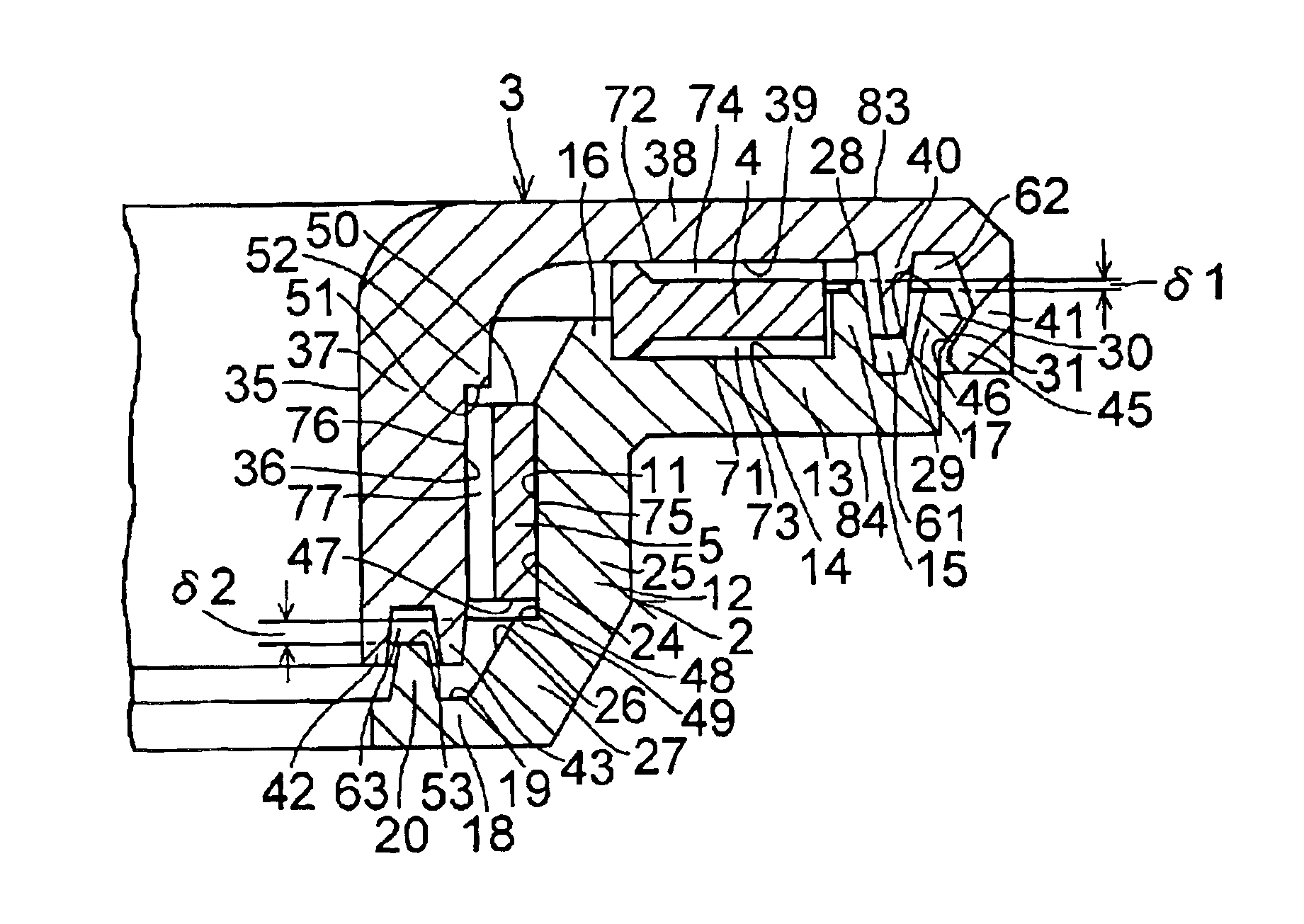
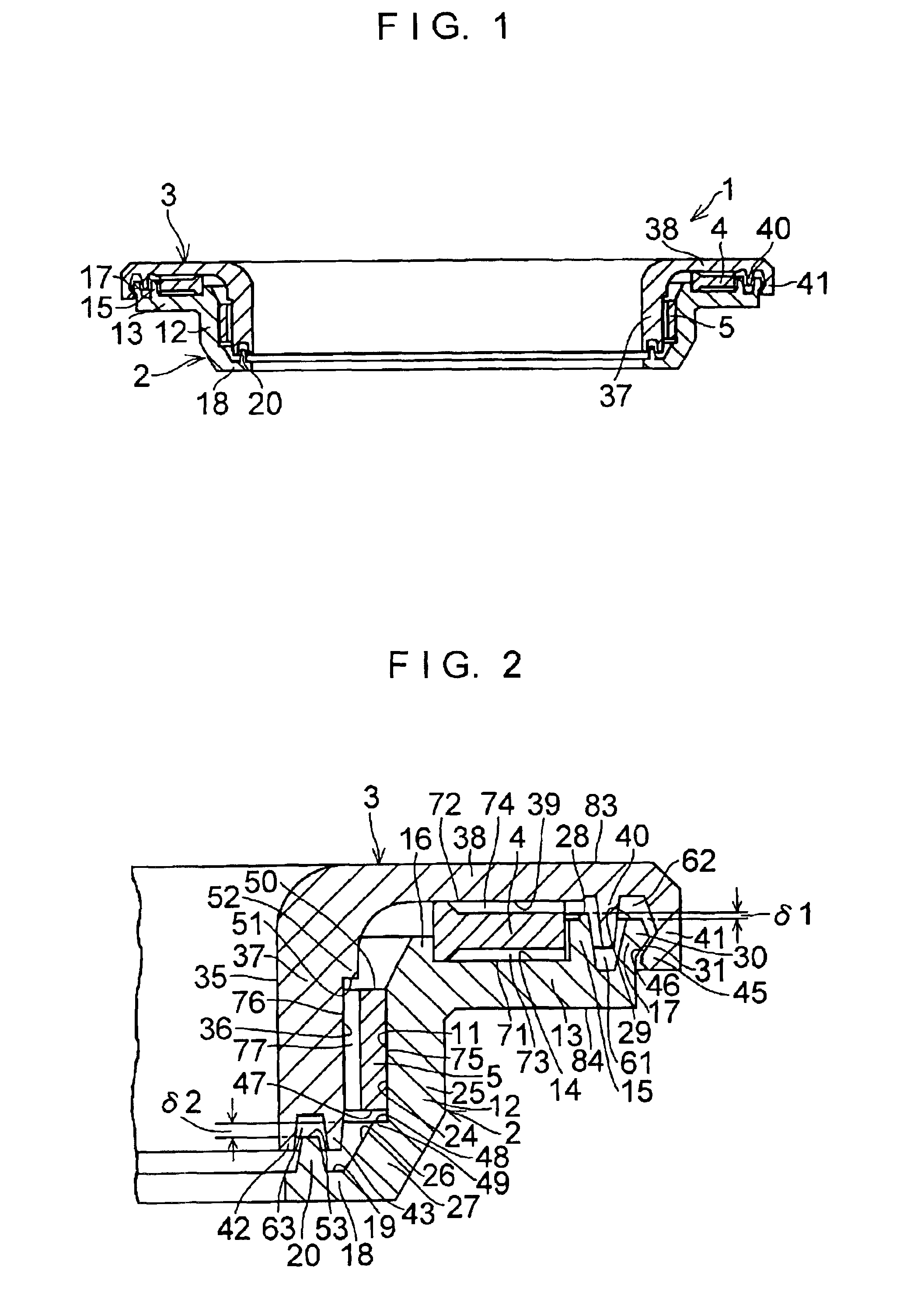
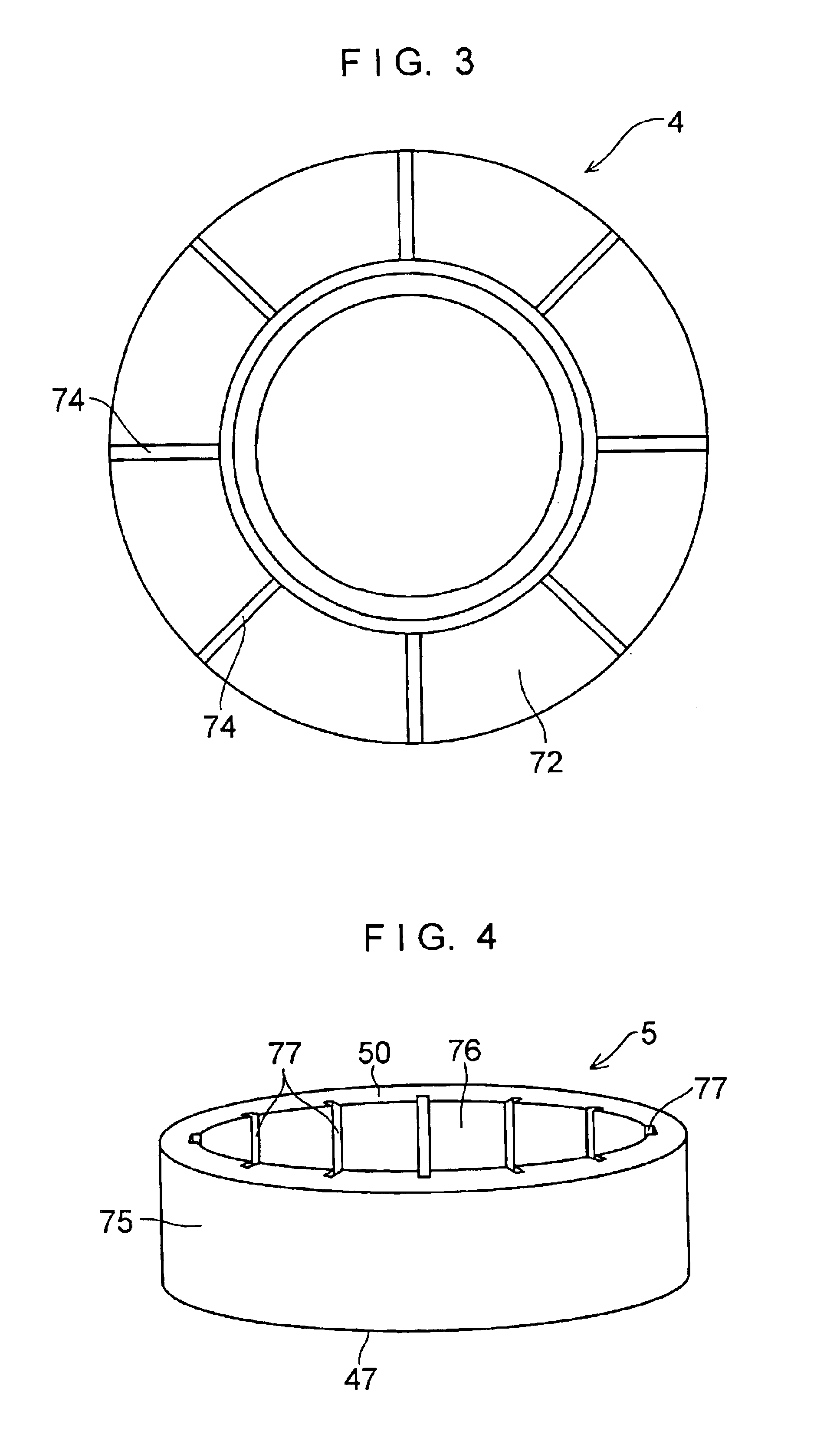
[0027]In FIGS. 1 to 4, a synthetic resin-made sliding bearing 1 in accordance with this embodiment is comprised of a synthetic resin-made lower casing 2, a synthetic resin-made upper casing 3 superposed on the lower casing 2, a synthetic resin-made disk-shaped thrust sliding bearing piece 4 disposed between the upper and lower casings 3 and 2, and a synthetic resin-made cylindrical radial sliding bearing piece 5 disposed between the upper and lower casings 3 and 2.

[0028]The lower casing 2 includes a tubular portion 12 having an inner peripheral surface 11, an annular plate portion 13 formed integrally with an end portion of the tubular portion 12, an annular projection 15 formed integrally with an outer side of an upper surface 14 of the annular plate portion 13, an annular projection 16 formed integrally with an inner side of the upper surface 14 of the annular plate portion 13, an annular engaging projection 17 formed integrally with an outer edge of the annular plate portion 13, ...


PUM

PropertyMeasurementUnit
steering forceaaaaaaaaaa
wear resistanceaaaaaaaaaa
shock resistanceaaaaaaaaaa

Abstract

A synthetic resin-made sliding bearing (1) includes a synthetic resin-made lower casing (2), a synthetic resin-made upper casing (3) superposed on the lower casing (2), a synthetic resin-made disk-shaped thrust sliding bearing piece (4) disposed between the upper and the lower casings (3) and (2), and a synthetic resin-made cylindrical radial sliding bearing piece (5) disposed between the upper and the lower casings (3) and (2).

Description

[0001]This application is the US national phase of international application PCT / JP02 / 01671 filed Feb. 25, 2002, which designated the US.TECHNICAL FIELD[0002]The present invention relates to a synthetic resin-made sliding bearing, and more particularly to a synthetic resin-made sliding bearing which is suitably incorporated in a strut-type suspension (Macpherson type) in a four-wheeled vehicle.BACKGROUND ART[0003]A strut-type suspension used in a front wheel of a four-wheeled vehicle generally has a structure in which a strut assembly incorporating a hydraulic shock absorber in an outer cylinder formed integrally with a main shaft is combined with a coil spring. In such suspensions, there is a type in which a piston rod of the strut assembly rotates and a type in which the piston rod does not rotate when the strut assembly rotates together with the coil spring on steering operation. In either type, there are cases where a synthetic resin-made sliding bearing in place of a rolling ba...

Claims


Application Information

Patent Timeline
Patent Type & Authority Patents(United States)
IPC IPC(8): F16C33/04F16C33/10F16C33/74F16C33/72F16C33/20F16C17/26F16C17/00F16C17/10F16F9/54
CPCF16C17/26F16C33/1065F16C33/20F16C33/74F16C17/10B60G2202/312B60G2204/128B60G2204/418B60G2204/4502F16C2361/53F16C2326/05F16C2208/60F16C2208/40F16C2208/66F16C2208/70F16C2208/76
Inventor UENO, ATSUSHIMIYATA, KAZUYUKI
Owner OILES CORP
Why Eureka
Try Eureka