Thread cutting tool having cutting teeth with stepped undercut flanks

a cutting tool and thread technology, applied in wood boring tools, forging/pressing/hammering apparatuses, forging/hammering/hammering machines, etc., can solve the problems of not being able to withstand the usual cutting force, and achieve the effect of avoiding the negative effect, avoiding and reducing the loss of cutting edg

Inactive Publication Date: 2005-07-19
SANDVIK INTELLECTUAL PROPERTY AB
View PDF9 Cites 13 Cited by
  • Summary
  • Abstract
  • Description
  • Claims
  • Application Information

AI Technical Summary

Benefits of technology

[0020]The present invention is furthermore particularly advantageously implemented in cutting tools where the groups of cutting teeth and the grooves for chippings are substantially axially parallel or have a very large helical pitch, because with these types of tool, the transport of the chippings by the grooves for chippings is often particularly quite poor, and the invention advantageously avoids the negative effects of the numerous chippings frequently present.

Problems solved by technology

An initial section of the flank disposed immediately behind the cutting edge still has the usual prior art configuration in order not to weaken the cutting edge area of the cutting tooth, because with a smaller wedge angle it could possibly be less able to withstand the usual cutting forces.
The same problem also occurs in principle with thread milling cutters that produce a simple bore when advanced and only cut the thread when reversed in an eccentric path of motion.

Method used


Image

  • Thread cutting tool having cutting teeth with stepped undercut flanks
  • Thread cutting tool having cutting teeth with stepped undercut flanks
  • Thread cutting tool having cutting teeth with stepped undercut flanks

Examples


Embodiment Construction

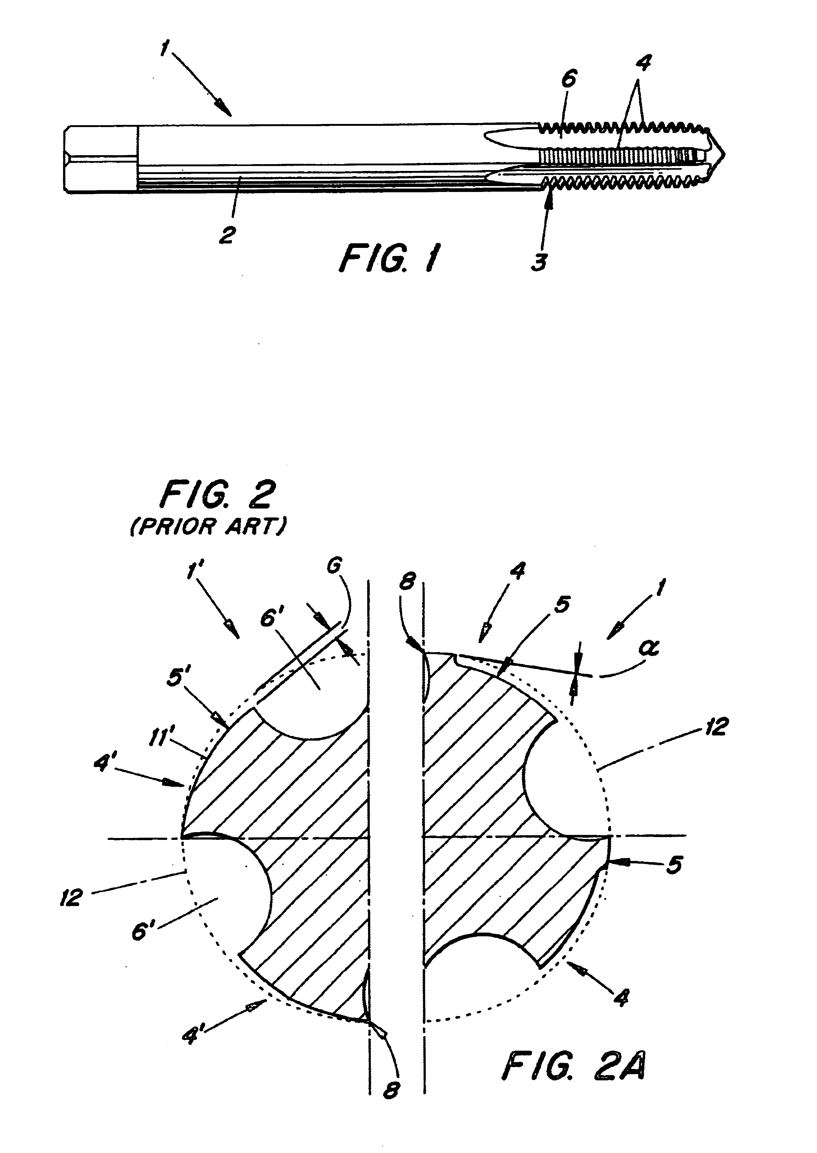
[0027]FIG. 1 shows the thread cutting tool, generally designated 1, in the form of a screw tapping tool that is provided with a shaft 2 and a cutting portion 3. The shaft 2 in this case is shown as a simple cylindrical shaft, but can, however, be of any other shape according to how the corresponding chuck or clamping chuck of a machine tool is configured. The cutting portion 3 is provided with several cutter rows 4 that are each composed of a group of cutting teeth 5, and has grooves for chippings 6 in between. In the present case, the chipping grooves 6 and the cutter rows 4 or respectively groups of cutting teeth are on a relatively steep helical curve.

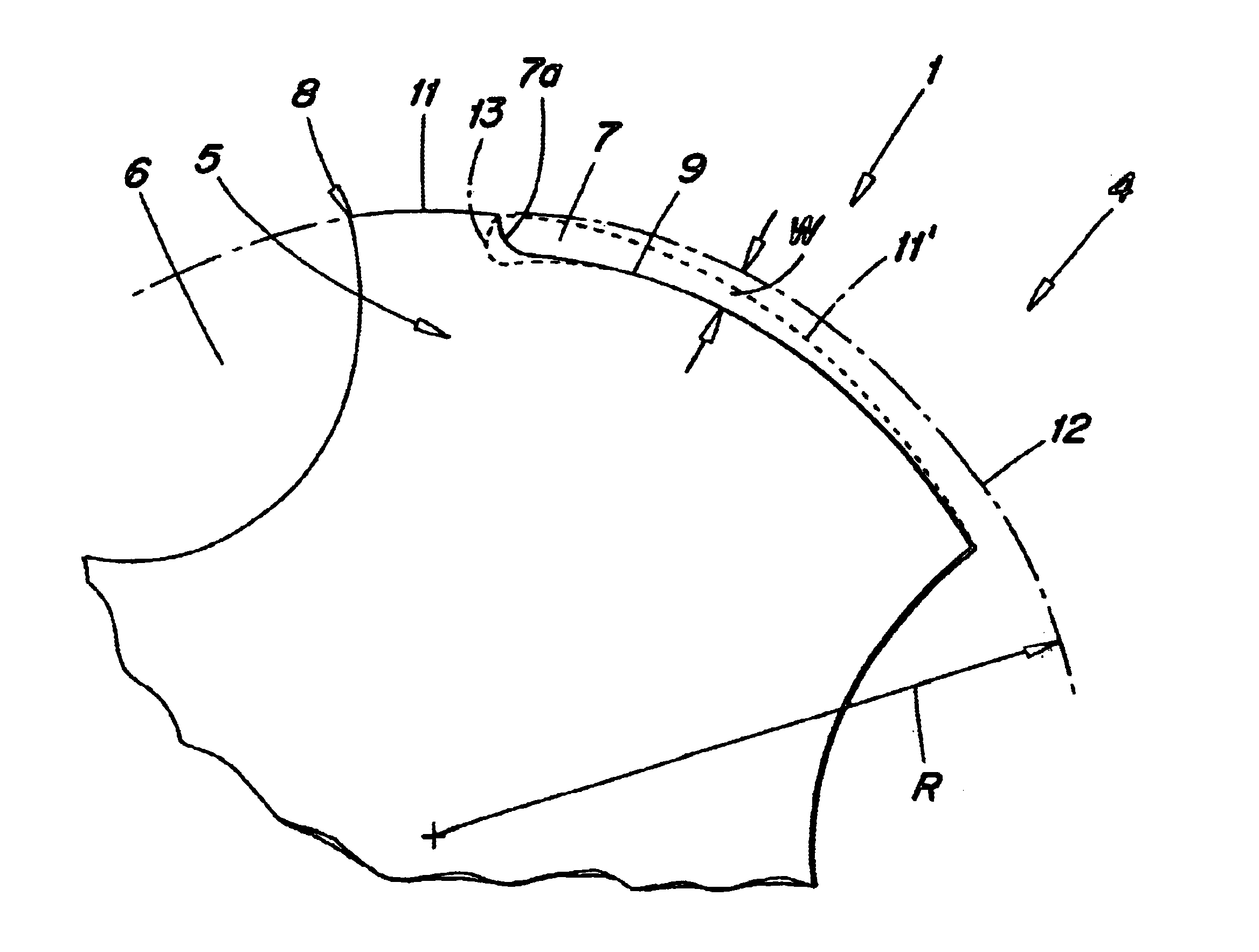
[0028]FIG. 2 is a cross-sectional view through the left half of a prior art thread cutting tool 1′, whereas FIG. 2a is a cross section through the right half of a thread cutting tool 1 according to the present invention.

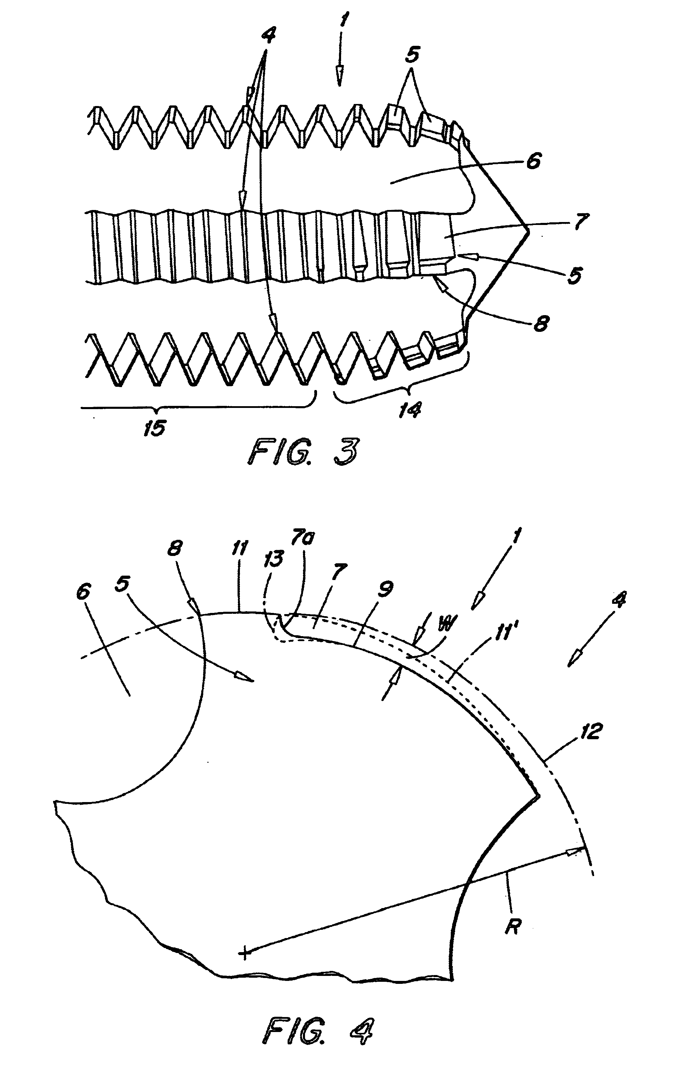
[0029]FIG. 3 shows an enlargement of the cutting portion 3 according to the invention. The cutting portion 3 is di...


PUM

PropertyMeasurementUnit
radial depthaaaaaaaaaa
clearance angleaaaaaaaaaa

Abstract

A thread cutting tool for cutting female threads includes a shaft and a cutting section composed of several groups of cutting teeth alternating with chip grooves. At least some of the teeth, preferably teeth disposed in a front region of the tool, have undercuts in their flanks which define radial steps, each step spaced circumferentially from a cutting edge of the respective tooth in order to form a space which facilitates the escape of cuttings.

Description

[0001]This application claims priority under 35 U.S.C. § 119 to Patent Application Serial No. 101 55 979.8 filed in Germany on Nov. 14, 2001, the entire content of which is hereby incorporated by reference.BACKGROUND[0002]The present invention relates to a thread cutting tool for cutting female threads, with a shaft and a cutting section that is composed of several axially parallel or spirally arranged cutter rows each provided with a group of cutting teeth and chip grooves arranged in between them.[0003]The term “thread cutting tool” generally includes so-called screw taps, and also certain types of thread milling cutters to the extent that they are for manufacturing female threads. Such a thread cutting tool either itself produces the thread bore, i.e., the core boring for a thread, or it is screwed into a previously prepared bore, the diameter of which is usually in proportion to the final thread diameter, depending on the material of the workpiece. The thread cutting tool is scr...

Claims


Application Information

Patent Timeline
Patent Type & Authority Patents(United States)
IPC IPC(8): B23G5/06B23G5/00
CPCB23G5/06Y10T408/90467Y10T408/9048
Inventor SCHWARZ, FRIEDRICH
Owner SANDVIK INTELLECTUAL PROPERTY AB
Why Eureka
Try Eureka