Supercharge Your Innovation With Domain-Expert AI Agents!

Gas turbine engine axial stator compressor

a compressor and axial stator technology, applied in the direction of machines/engines, stators, liquid fuel engines, etc., can solve the problems of overall degradation of gas turbine engine efficiency, reduce stray leakage, reduce embedding stresses, and improve the shock absorption of the vane assembly

Inactive Publication Date: 2005-07-19
SN DETUDE & DE CONSTR DE MOTEURS DAVIATION S N E C M A
View PDF3 Cites 3 Cited by
  • Summary
  • Abstract
  • Description
  • Claims
  • Application Information

AI Technical Summary

Benefits of technology

[0006]The second goal of the present invention is a compressor stator providing improved dynamic behavior of the arcuate segments.
[0008]Due to this geometry, heat conduction is lowered because the connection between the hot inner sheetmetal and the outer sheetmetal is implemented uniquely by the honeycomb component which restricts the size of the thermally conducting and contacting surfaces between the hot inside and the cold outside. The temperature of the outer sheetmetal is substantially lower than that of the inner sheetmetal. This is even more the case for the external annular frame. Since the brazed arcuate segments provide a good seal, the air flow in the cavities between the outer and inner sheetmetals is restricted, and, as a result, convective heat loss is decreased.
[0011]This rigid affixation both improves the dynamic behavior of the arcuate segments and permits the inner sheetmetal to expand freely. Consequently, the leakage between upstream and downstream is reduced and compressor efficiency is increased.
[0013]These two sheetmetals are rigidly connected to each other by means of the brazed honeycomb component and they are sufficiently apart from each other to restrict embedding stresses and to improve vane assembly shock absorption.
[0014]The honeycomb arcuate segments allow reducing stray leakage between downstream and upstream, resulting in higher compressor efficiency.

Problems solved by technology

The conventional remedy includes cooling the assembly by tapping a cooler gas flow from a region upstream of the compressor, which results, however, in an overall degradation of gas turbine engine efficiency.

Method used


Image

  • Gas turbine engine axial stator compressor
  • Gas turbine engine axial stator compressor
  • Gas turbine engine axial stator compressor

Examples


Embodiment Construction

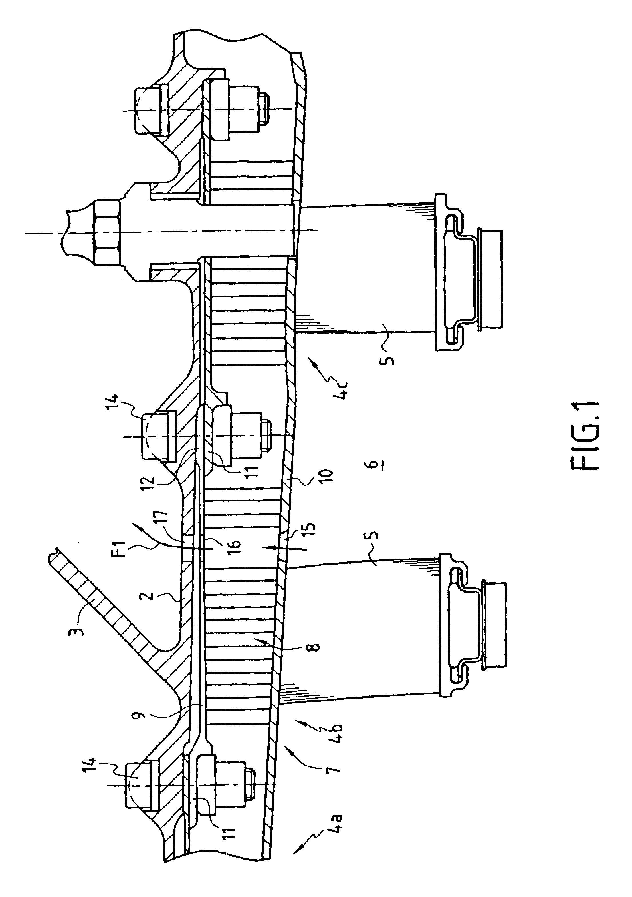
[0019]FIG. 1 shows a portion of a turbojet-engine compressor stator which, inside an external casing defining within it a cold-air flow path, contains a rigid annular structure 2 that is connected by frustoconical walls 3 to the external casing, furthermore a plurality of axially juxtaposed rings 4a, 4b, 4c that are concentrically configured inside the annular structure 2. Each ring supports an annulus of stationary vanes 5 running radially inward. An omitted rotor flange is fitted with annuli of moving blades and is configured coaxially inside the rings 4a, 4b, 4c, the annuli of moving blades alternating axially with the annuli of stationary vanes in the flowpath 6 of the gas compressed by the compressor.

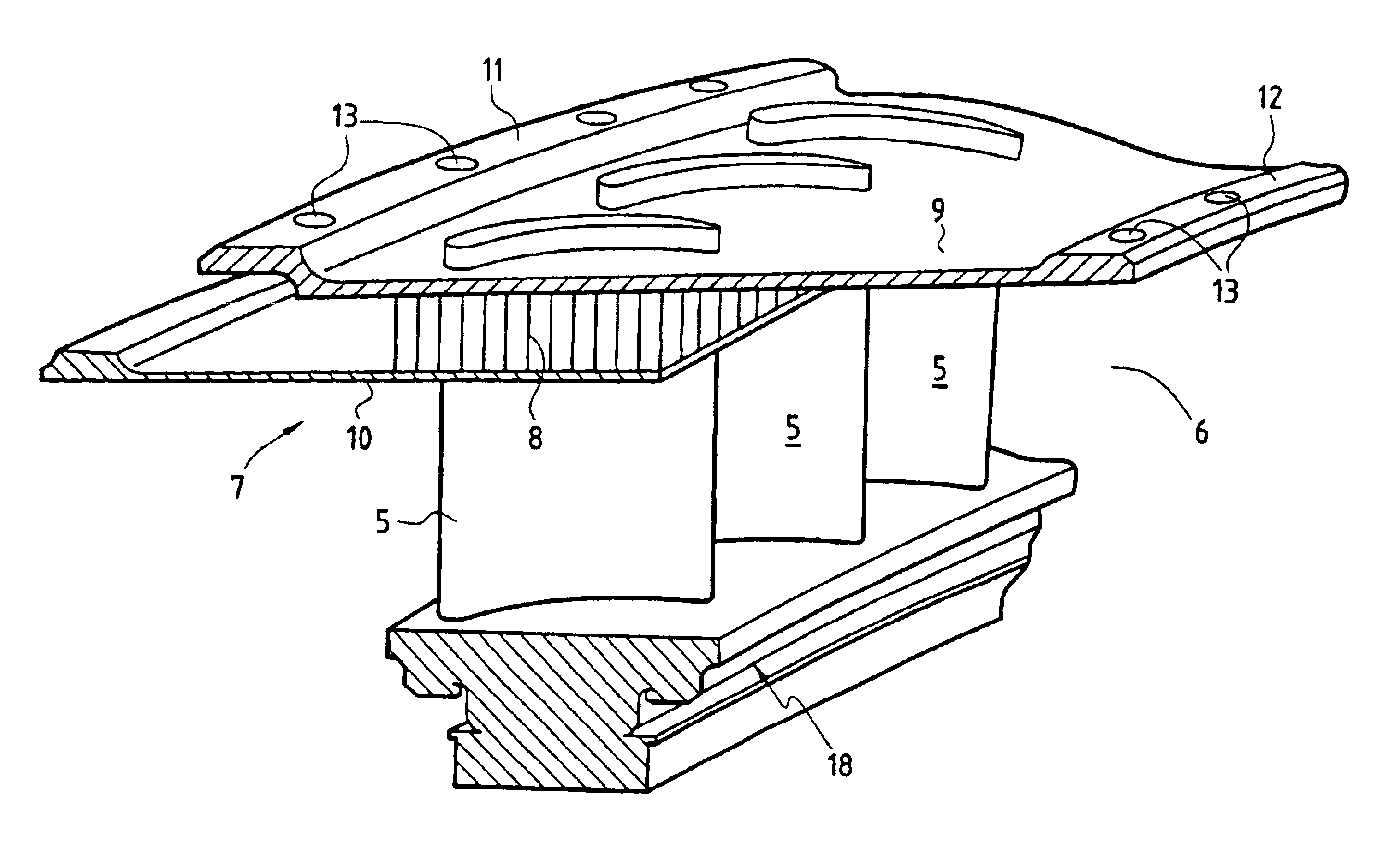
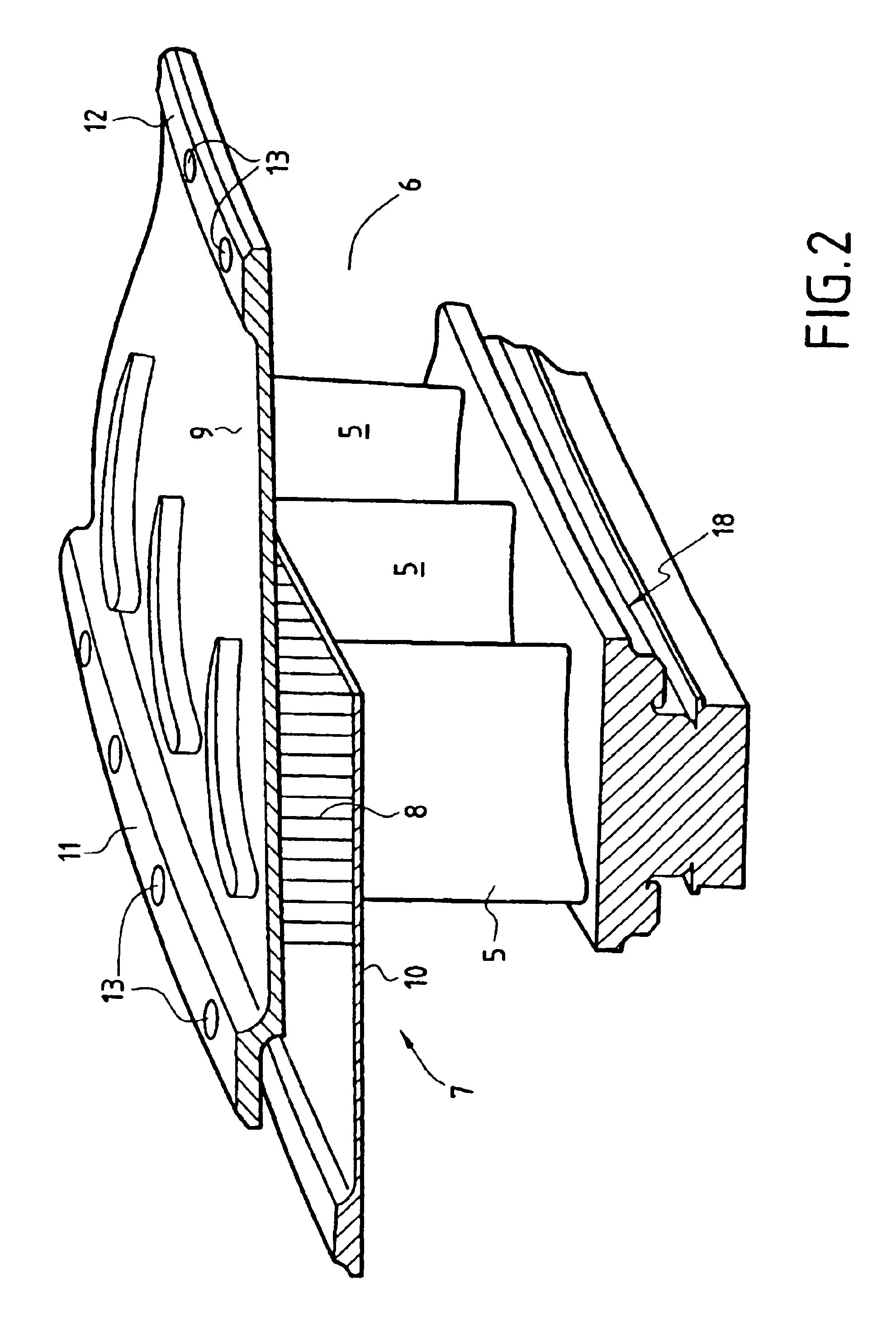
[0020]To mount the stator around the rotor, each ring consists of a plurality of circumferentially juxtaposed arcuate segments 7.

[0021]According to the invention and as shown in FIGS. 1 and 2, each arcuate segment 7 consists of a honeycomb component 8 sandwiched between an outer sh...


PUM


Abstract

The invention relates to an axial compressor stator for a gas turbine, the stator having a rigid, external, annular frame and axially juxtaposed rings configured within the frame and bearing annuli of stationary vanes. The rings are defined by arcuate segments affixed to the frame. The inside walls of the arcuate segments externally define the aerodynamic conduit for the compressed gaseous fluid. The arcuate segments are brazed segments that include a honeycomb component sandwiched between an inner sheetmetal bounding the aerodynamic conduit and an outer sheetmetal. The outer sheetmetal solely connects the arcuate segments to the frame.

Description

BACKGROUND OF THE INVENTION[0001]The present invention relates to gas turbine compressors and in particular to turbojet engine compressors.[0002]More specifically, it relates to an axial compressor stator comprising a rigid, external annular frame and axially juxtaposed rings which are configured radially inside the frame and which support stationary annuli of vanes running radially inward, these annuli including arcuate segments affixed to the frame by appropriate fastening means and externally defining the compressed-gasses' aerodynamic conduit.[0003]In general the arcuate segments comprise an inside wall bounding the aerodynamic conduit and radial ribs pointing outward and resting against the external annular frame, the ribs configured with bases to affix by means of bolts the arcuate segments on the frame. The stationary vanes are affixed in an orifice in the inner wall.[0004]The compressed gases of a turbojet engine high-pressure compressor are hot. The inside walls of the arcu...

Claims


Application Information

Patent Timeline
IPC IPC(8): F01D25/24F01D9/04F04D29/40F04D29/54F02C7/24F04D19/02F04D29/58
CPCF01D9/044F01D25/246F04D29/542
Inventor CARON, STEPHANEDEBENEIX, PIERREGUEROUT, PHILIPPE
Owner SN DETUDE & DE CONSTR DE MOTEURS DAVIATION S N E C M A
Features
  • R&D
  • Intellectual Property
  • Life Sciences
  • Materials
  • Tech Scout
  • Unparalleled Data Quality
  • Higher Quality Content
  • 60% Fewer Hallucinations
Learn More