Light-generating instrument

Active Publication Date: 2005-07-19
THE KERR
View PDF20 Cites 39 Cited by
  • Summary
  • Abstract
  • Description
  • Claims
  • Application Information

AI Technical Summary

Benefits of technology

[0010]Accordingly, an objective of the invention is to provide a light-generat

Problems solved by technology

A significant drawback in the use of such light-generating instruments is that the source of electrical power is the inconvenience of connecting the instrument to an electrical outlet and the inconveniences of the electrical c

Method used


Image

  • Light-generating instrument
  • Light-generating instrument
  • Light-generating instrument

Examples


Embodiment Construction

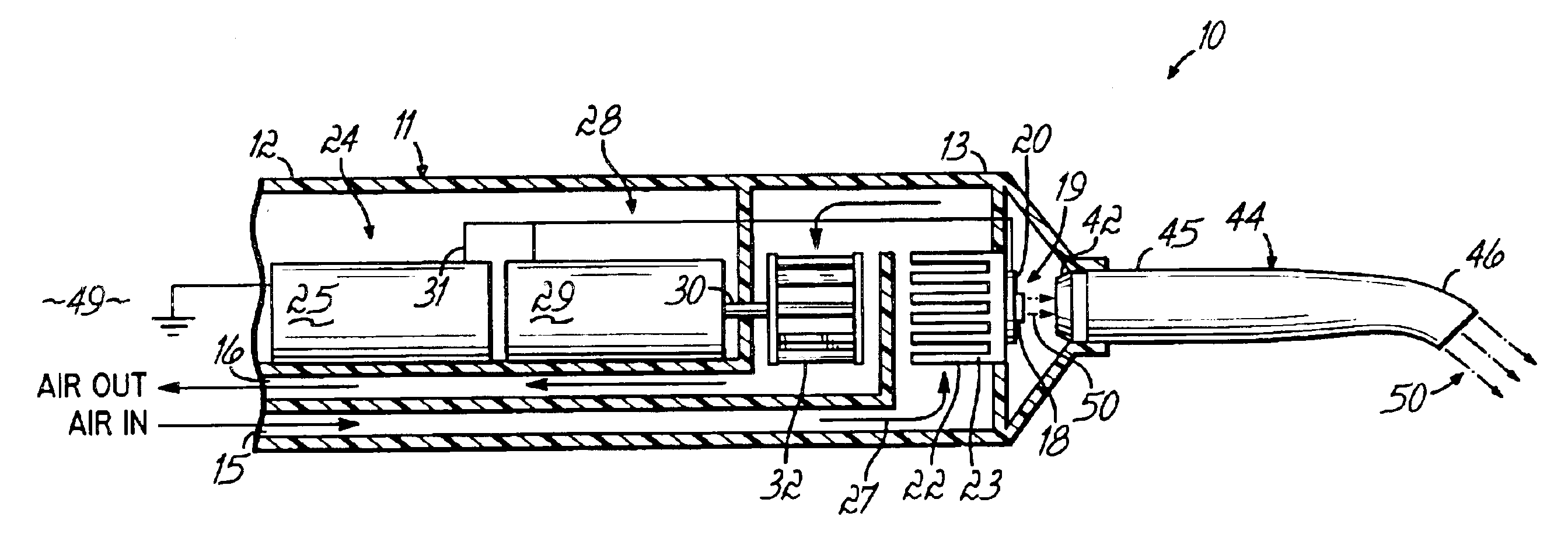
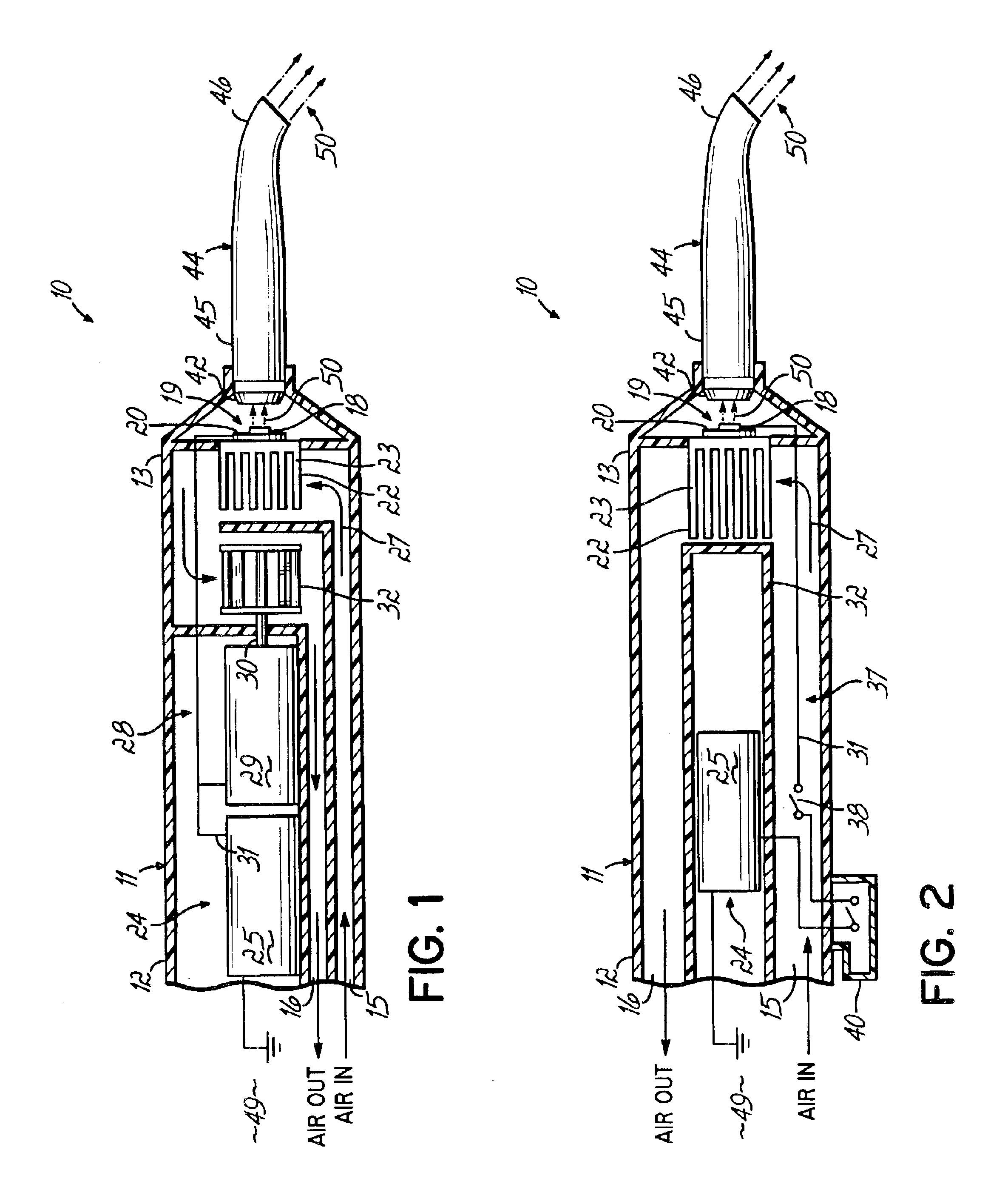
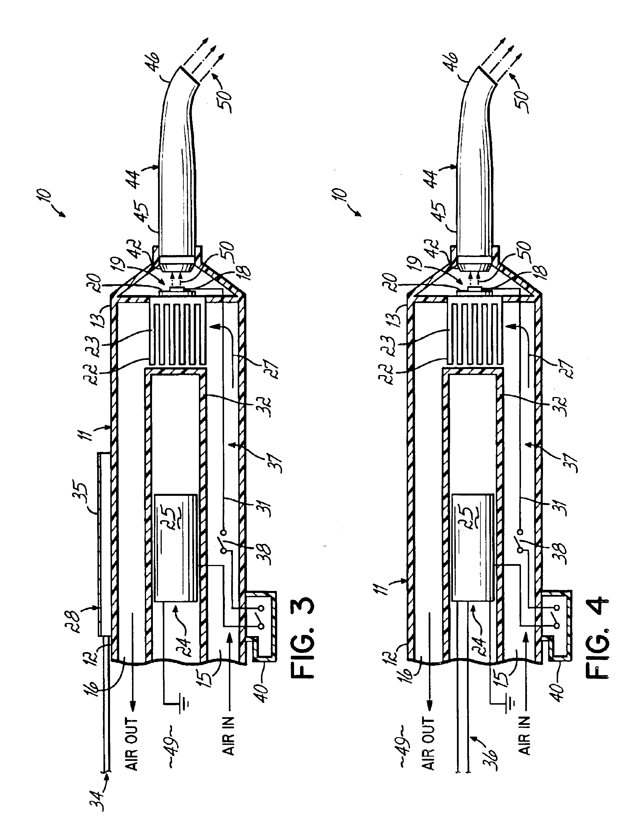
[0028]FIGS. 1-4 illustrate embodiments of light-generating instruments 10 used for curing light-curable compounds, and in particular, dental light-curable compounds. Each embodiment of the light-generating instrument 10 generally comprises a light generator 19 and a power system 24, as depicted in the diagram of FIG. 5. The alternative embodiments include additional physical components, some of which are illustrated in FIGS. 1-4 and discussed in greater detail below. The power system 24 includes a power supply 25 that supplies electrical energy to operate the light generator 19 and a cooling source 27 to supply cooling fluid, such as air, that cools the light generator 19. The energy and cooling fluid may be transferred to power system 24 through an interface 47 from a dental chair 56 in a dental treatment site 49. FIG. 6 illustrates an embodiment having the dental chair 56 interfaced via connectors 60 to instrument 10 to provide cooling air and / or an energy stimulus, such as air fl...


PUM


Abstract

The invention relates to light-generating instruments, which are small, compact and convenient to use. More particularly, the light-generating instruments are generally powered by air, electricity, or light provided by the operating unit, such as the dental chair. Air, electricity, and light provided by the dentist's chair allow for convenience to the dentist while eliminating potential risks and hazards associated with use of an electrical cord to power the instrument.

Description

FIELD OF THE INVENTION[0001]The present invention generally relates to a light-generating instrument and method for curing light-curable compounds. More particularly, the invention provides a power system for the generation of light particularly useful for curing light-curable dental adhesives.BACKGROUND OF THE INVENTION[0002]Light-curable compounds, such as adhesives and bonding or filling compounds, are widely used to attach objects to surfaces or to fill gaps or other openings. Such curable compounds are generally available in a semi-solid state and are manipulated and positioned on the surface or in the gap as desired to be hardened or cured into a more solid state. Curing or hardening is generally a chemical polymerization process, which is promoted and driven by various curing conditions and factors. For example, a semi-solid compound or component thereof, maybe cured by exposure to air or to energy, such as heat or light energy.[0003]Today, most adhesive and filling compounds...

Claims


Application Information

Patent Timeline
IPC IPC(8): A61C13/15A61C13/00
CPCA61C19/004Y10S362/80Y10S362/804
Inventor GILL, OWEN J.SHELLARD, EDWARD ROBERT
Owner THE KERR
Why Eureka
Try Eureka