Accurate time measurement system circuit and method

Inactive Publication Date: 2005-07-19
TEXAS INSTR INC
View PDF7 Cites 6 Cited by
  • Summary
  • Abstract
  • Description
  • Claims
  • Application Information

AI Technical Summary

Benefits of technology

[0010]The invention provides technical advantages including but not limited to improved accuracy of time measurements, simplified testing under changing conditions, reduced influence of external factors, and extending the utility of existing test equipment. These and o

Problems solved by technology

Inaccuracies in the measurement of a signal are caused in part by differences in the rising edge and falling edge propagation delays.
Further problems exist with conventional time measurement circuits and methods making use of calibration circuits and measurement offsets.
Changes

Method used


Image

  • Accurate time measurement system circuit and method
  • Accurate time measurement system circuit and method
  • Accurate time measurement system circuit and method

Examples


Example

[0017]References in the detailed description correspond to like references in the figures unless otherwise noted. Like numerals refer to like parts throughout the various figures. Descriptive and directional terms used in the written description such as top, bottom, left, right, etc., refer to the drawings themselves as laid out on the paper and not to physical limitations of the invention unless specifically noted. The drawings are not to scale and some features of embodiments shown and discussed are simplified or exaggerated for illustrating the principles, features, and advantages of the invention.

DETAILED DESCRIPTION OF PREFERRED EMBODIMENTS

[0018]In general, the invention provides circuits, systems, and methods for making accurate measurement of device time output signals. It should be understood that the invention may be practiced for the testing of various devices using various commercially available test equipment familiar to those skilled in the arts.
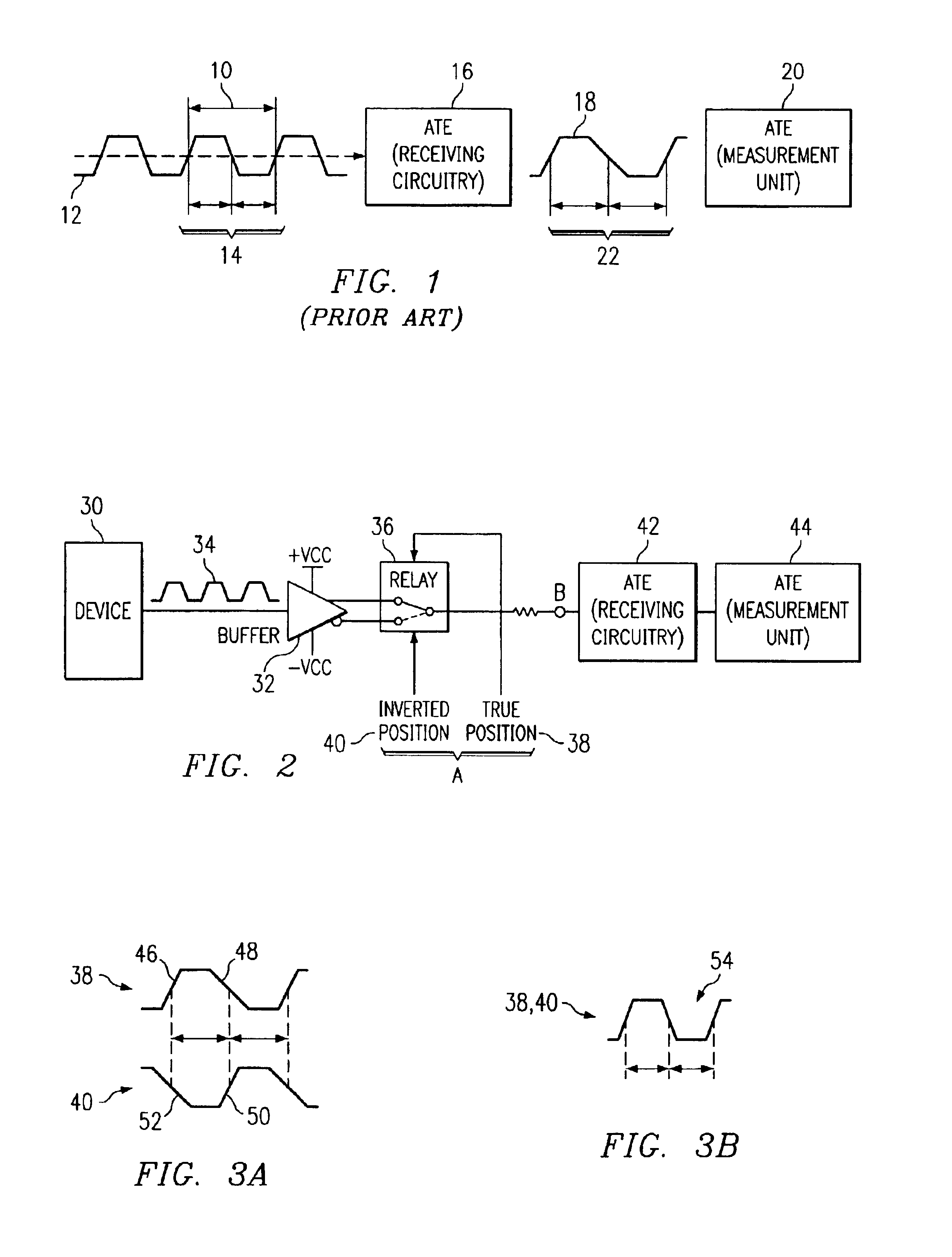
[0019]Representatively i...


PUM


Abstract

Disclosed is a method of measuring the time signal of an electronic device including steps for measuring a true signal and an inverted signal. The measured true path signal and inverted path signal are combined to reduce measurement error and provide an accurate measurement of the time signal of the device under test. Also disclosed is an interface for use between a device-under-test and test equipment. The interface includes means for alternately switching a time signal from the device-under-test to provide a true signal path and an inverted signal path for measurement. A system embodiment of the invention is also disclosed in which an interface and measuring means are used to alternately measure and combine a true signal and an inverted signal to provide an accurate time measurement result.

Description

TECHNICAL FIELD[0001]The invention relates to providing accurate time measurements for testing electronic devices. More particularly, the invention provides methods, circuits, and systems for improved device output time signal test measurements.BACKGROUND OF THE INVENTION[0002]The accuracy of any time measurement circuit is impacted by skew and propagation delays in the path of the signal to be measured. Inaccuracies in the measurement of a signal are caused in part by differences in the rising edge and falling edge propagation delays. It is known in the arts to use calibration circuits or software-generated offsets based on mathematical predictions modeling circuit characteristics in an attempt to produce accurate time measurements. Using such techniques, accuracy of plus or minus 5 nanoseconds is sometimes achievable under certain conditions.[0003]The problem of hardware distortion of a time signal to be measured is illustrated in FIG. 1. The period 10, or frequency of a device ti...

Claims


Application Information

Patent Timeline
IPC IPC(8): G01R31/3193G01R31/28
CPCG01R31/31937G01R31/31725
Inventor PATEL, GUNVANT T.FLORES, NICHOLAS
Owner TEXAS INSTR INC
Why Eureka
Try Eureka