Method and apparatus for magnetic coupling

Active Publication Date: 2005-07-19
MACKEN JOHN A
View PDF1 Cites 29 Cited by
  • Summary
  • Abstract
  • Description
  • Claims
  • Application Information

AI Technical Summary

Benefits of technology

[0018]A further object or feature of the present invention is a new and improved magnetic coupling device that permits accurate posit

Problems solved by technology

However, when a magnet is attached to a ferromagnetic material, such as a piece of steel there are several characteristics which are undesirable for specific applications.
First, the release characteristics are undesirable when an ordinary magnet is attached to a ferromagnetic surface such as steel.
Second, ordinary magnets do not position themselves accurately when they attach to steel.

Method used


Image

  • Method and apparatus for magnetic coupling
  • Method and apparatus for magnetic coupling
  • Method and apparatus for magnetic coupling

Examples


Example

[0043]Referring to FIGS. 1 through 17, wherein like reference numerals refer to like components in the various views, there is illustrated therein a new and improved magnetic coupling device, generally denominated 10 herein.

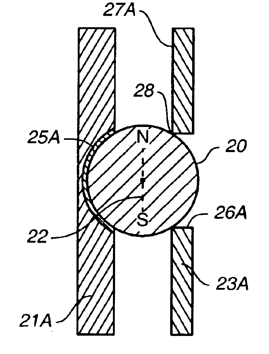
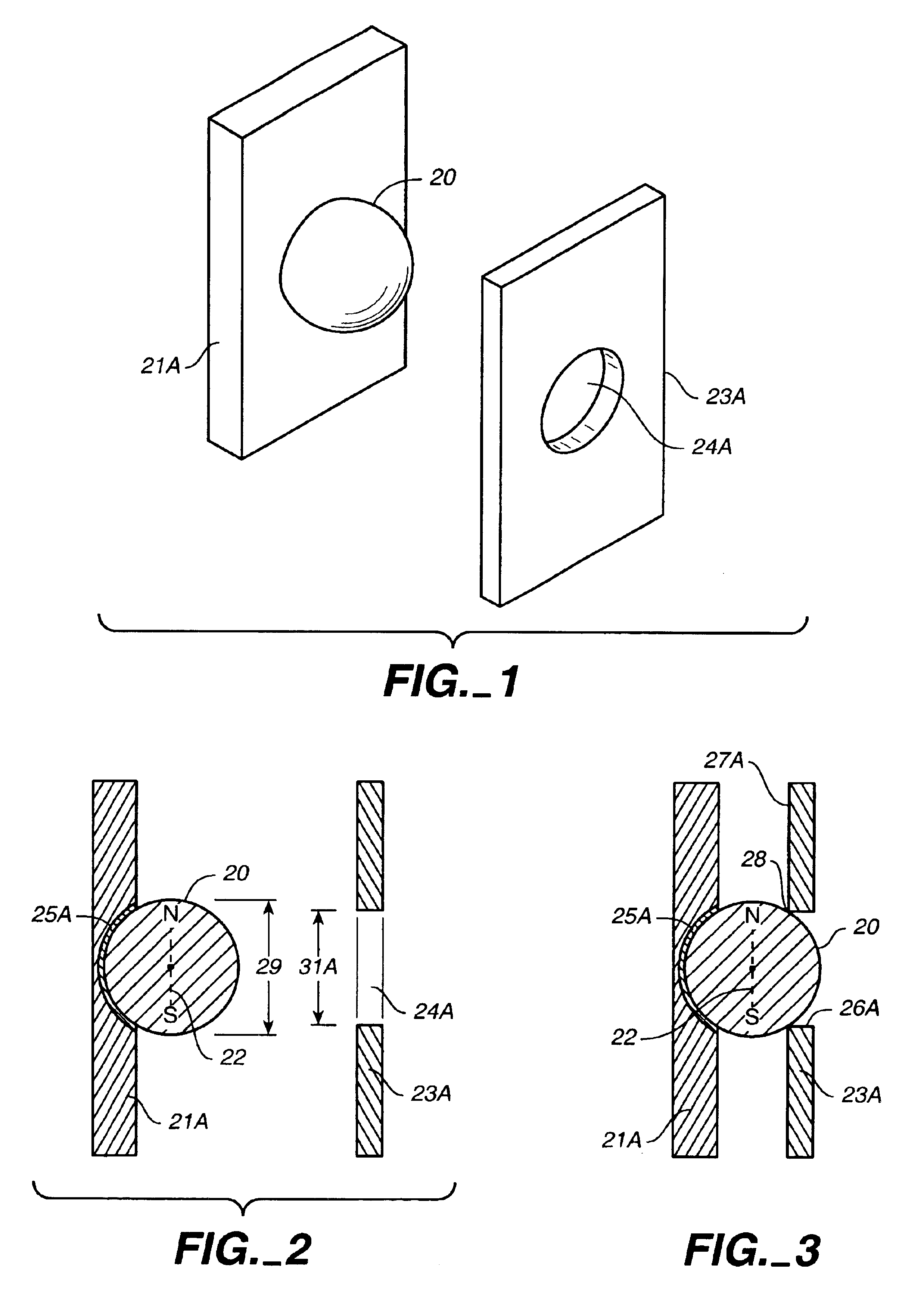
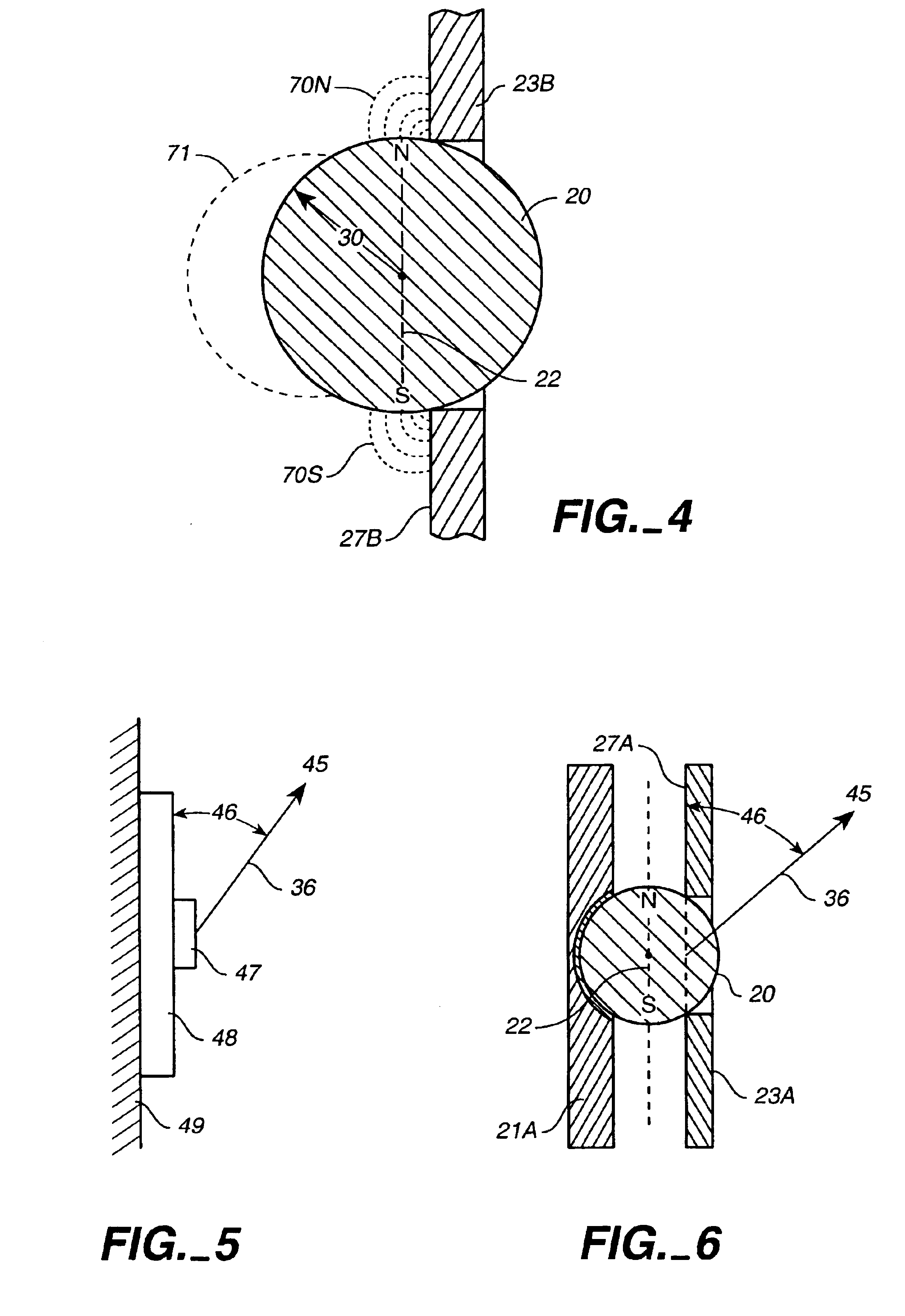
[0044]The advent of high strength rare earth magnets has resulted in new shapes and new characteristics for permanent magnets. One of the new shapes is the spherical permanent magnet. Typically, the spherical rare earth magnets (particularly the NdFeB magnets) are magnetized so that they exhibit a “focused magnetic field”. This is to say that inside the spherical magnet, the magnetic flux lines are not parallel. Instead, these lines tend to focus towards the North and South Poles of the magnet. The result of this magnetic focusing is that the spherical magnets can achieve a particularly strong magnetic field strength at the North Pole and South Pole of the spherical magnet. Experiments described here were made utilizing spherical rare earth magnets with focused m...


PUM


Abstract

The invention is a magnetic coupling device that utilizes a supported spherical magnet to attach to a hole in a ferromagnetic object. The hole shape and the orientation of the spherical magnet are predetermined to form a relatively strong magnetic attachment. The magnetic coupling device exhibits unique characteristics such as angular tolerance, precise positioning and controllable release characteristics.

Description

CROSS REFERENCE TO RELATED APPLICATIONS[0001]Not applicable.STATEMENT REGARDING FEDERALLY SPONSORED RESEARCH OR DEVELOPMENT[0002]Not applicable.REFERENCE TO A MICROFICHE APPENDIX[0003]Not applicable.TECHNICAL FIELD[0004]The present invention relates generally to magnetic couplers, attachment devices and fasteners, and more specifically to an improved magnetic coupling apparatus with desirable release characteristics, accurate positioning and angular flexibility.BACKGROUND INFORMATION AND DISCUSSION OF RELATED ART[0005]Magnets have long been used as a means for making a temporary connection between two components. However, when a magnet is attached to a ferromagnetic material, such as a piece of steel there are several characteristics which are undesirable for specific applications.[0006]First, the release characteristics are undesirable when an ordinary magnet is attached to a ferromagnetic surface such as steel. It is about six times easier to slide the magnet sideways across the s...

Claims


Application Information

Patent Timeline
IPC IPC(8): H01F7/02
CPCH01F7/0242H01F7/0252H01F7/0263
Inventor MACKEN, JOHN A.
Owner MACKEN JOHN A
Why Eureka
Try Eureka