Dimming mirror with blind zone sub-mirror and indicator

Active Publication Date: 2005-07-19
MAGNA MIRRORS OF AMERICA
View PDF21 Cites 137 Cited by
  • Summary
  • Abstract
  • Description
  • Claims
  • Application Information

AI Technical Summary

Benefits of technology

[0016]The recognition enhancement device can also comprise an electrochromic layer adapted to reduce the intensity of light transmitted from the object and reflected from the second reflective element. The el

Problems solved by technology

Even with a spotter mirror, the driver may fail to utilize the spotter mirror, or may not be sufficiently alerted to the necessity of using the spotter mirror, and a collision may ensue with a vehicle in the operator's blind zone.
Prior art spotter mirrors also suffer from another limitation.
Light impinging on the spotter mirror element from behind the vehicle, particularly during nighttime driving, can become distorted and r

Method used


Image

  • Dimming mirror with blind zone sub-mirror and indicator
  • Dimming mirror with blind zone sub-mirror and indicator
  • Dimming mirror with blind zone sub-mirror and indicator

Examples


Embodiment Construction

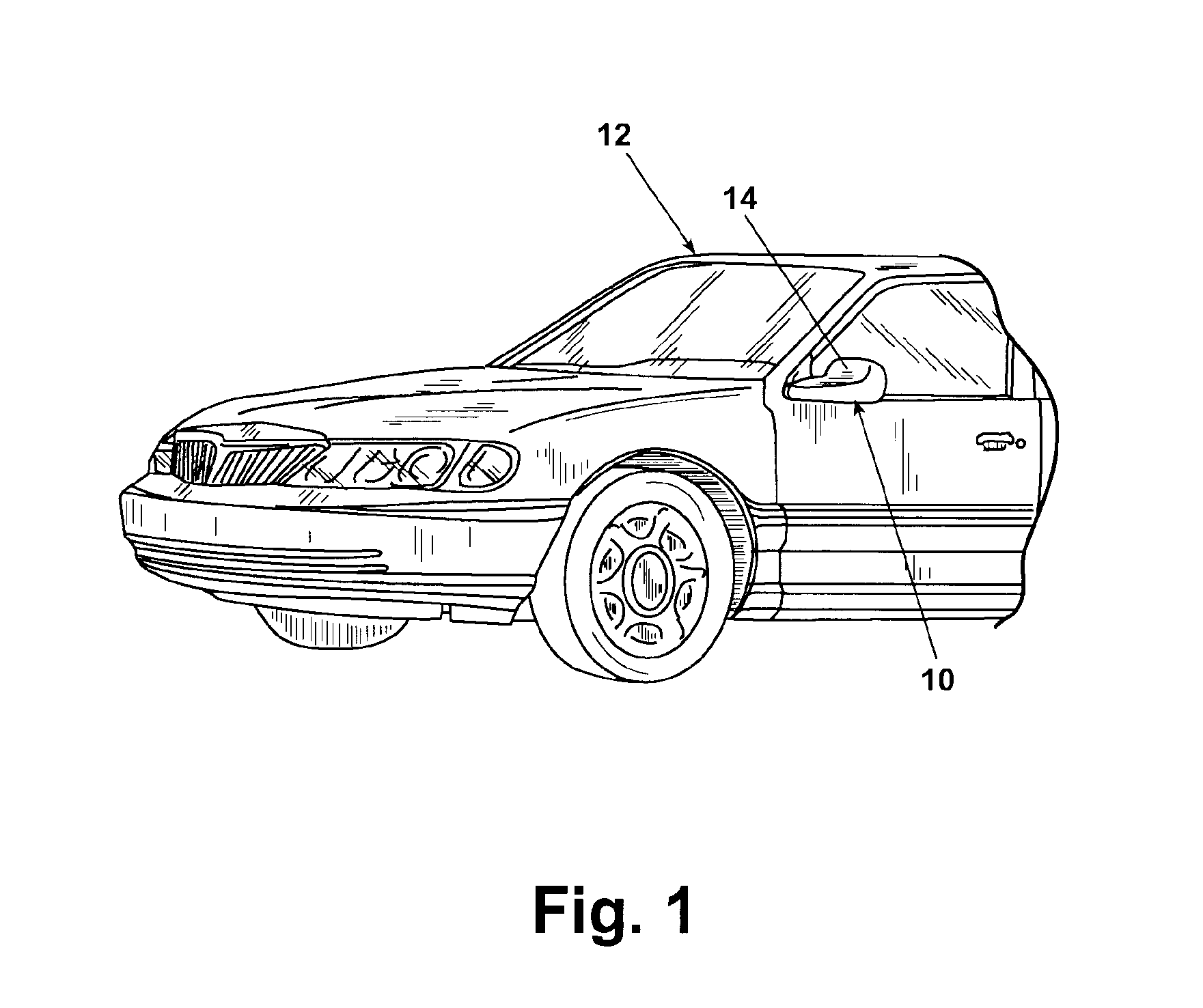
[0040]As shown in FIG. 1, a rearview mirror system 10 according to the invention is installed on an automotive vehicle 12 on or near the front of the driver's side door. An identical mirror system can be similarly mounted to the vehicle 12 on the passenger's side. The description of the structure and operation of the mirror system presented hereinafter will be equally applicable to both mirror systems.

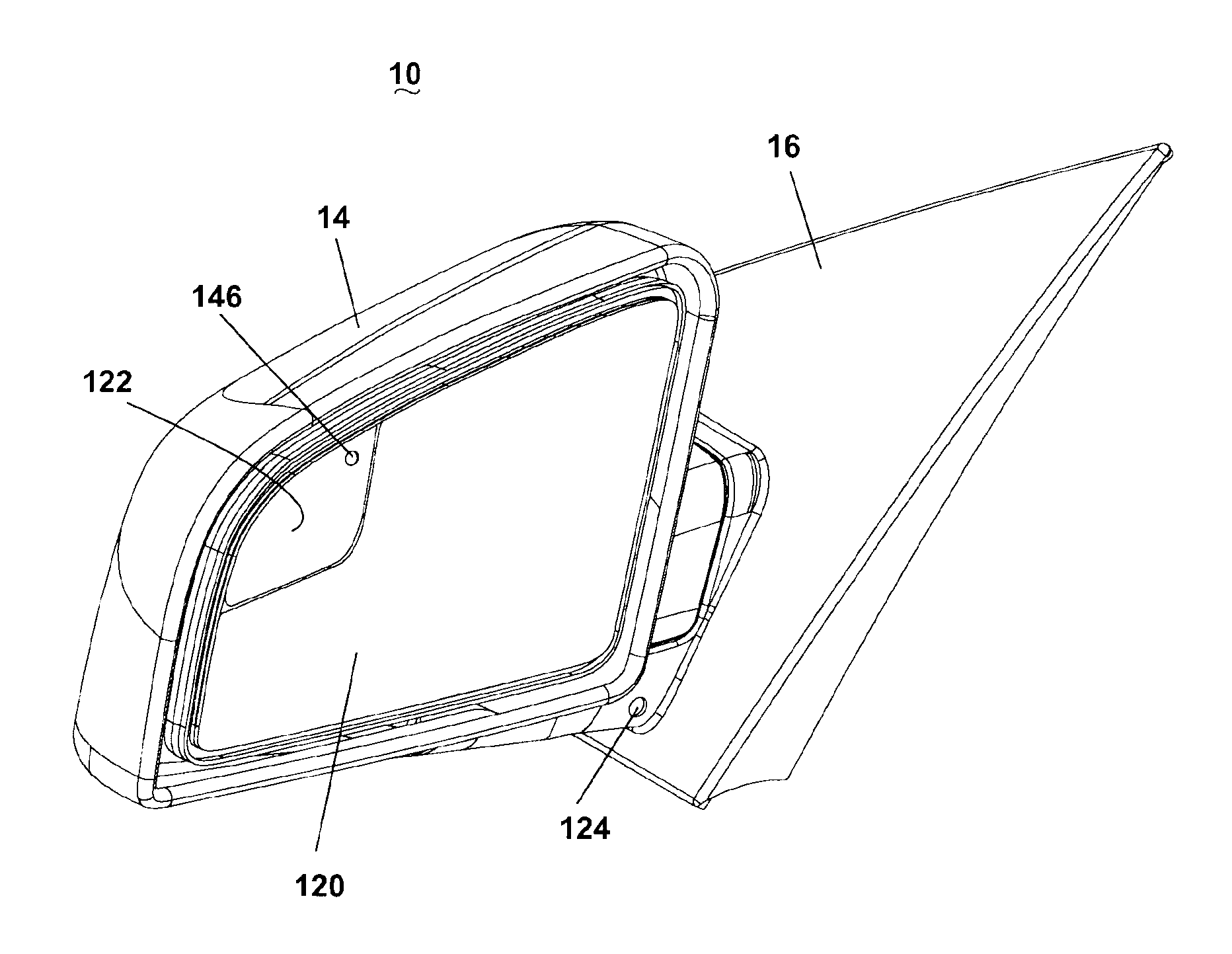
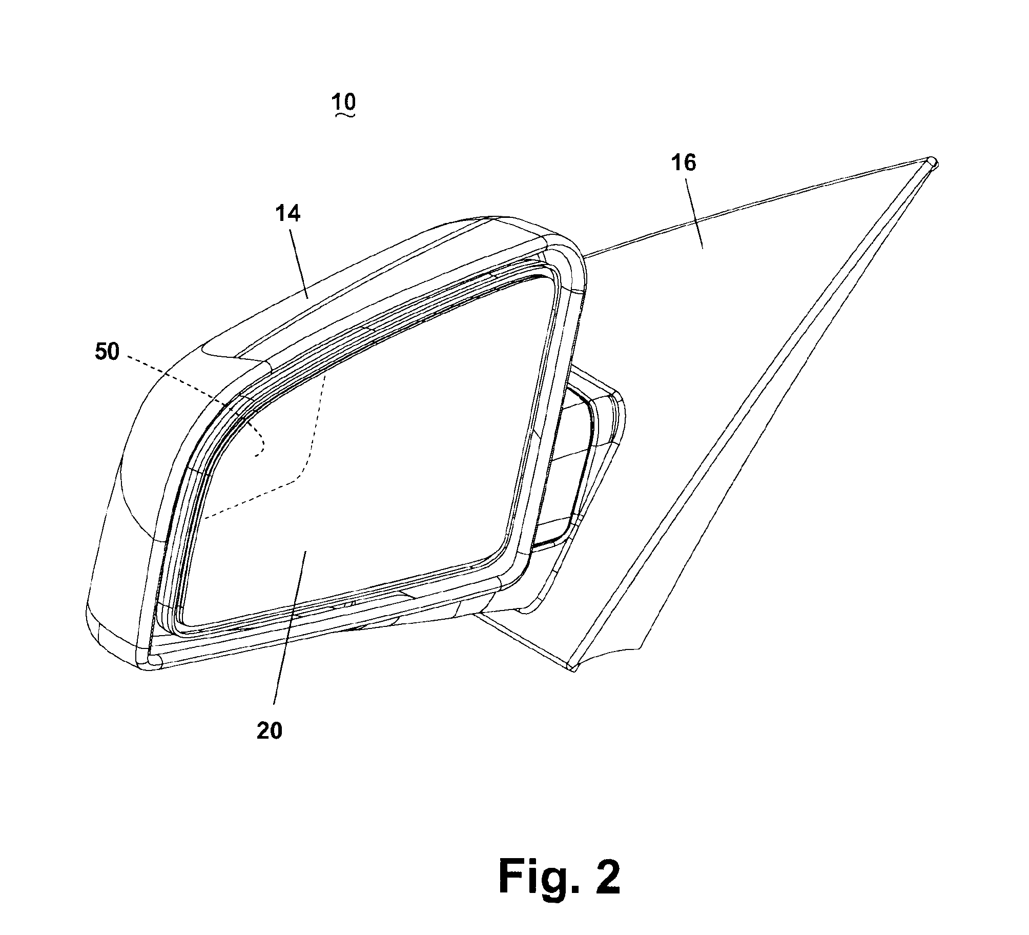
[0041]As shown also in FIGS. 2 and 3, the rearview mirror system 10 comprises several elements of a well-known rearview mirror assembly, including a shell 14 and a reflective element assembly 20, which are mounted to the vehicle 12 in a generally conventional manner through a base 16 and a mounting frame 18.

[0042]The reflective element assembly 20 comprises a multi-component mirror system. Referring to FIG. 4, the reflective element assembly 20 comprises a reflective element carrier 30 and a spotter mirror 50. The reflective element carrier 30 is a generally plate-like structure having...


PUM


Abstract

A rearview mirror system comprises a spotter mirror for providing an image of an object in a vehicle's blind zone to the vehicle's operator. A recognition enhancement device is provided with the spotter mirror for drawing the attention of the driver to the spotter mirror when an overtaking vehicle enters the driver's blind zone. The signaling display is activated by a sensing system which senses the presence of the overtaking vehicle in the blind zone. An electrochromic element is incorporated into the spotter mirror to reduce the intensity of light transmitted from the object and reflected from the spotter mirror. Activation of the electrochromic element to darken the spotter mirror will induce the operator to observe the object in the spotter mirror.

Description

CROSS REFERENCE TO RELATED APPLICATIONS[0001]This application claims the benefit of U.S. provisional applications Ser. Nos. 60 / 319,545, filed Sep. 12, 2002, and 60 / 319,638, filed Oct. 21, 2002, which are incorporated herein in their entirety.BACKGROUND OF INVENTION[0002]1. Field of the Invention[0003]The invention relates to mirrors for automotive vehicles. In one aspect, the invention relates to a mirror with a blind zone sub-mirror associated with a recognition enhancement device initiated by the detection of an overtaking vehicle entering the vehicle operator's blind zone. In another aspect, the invention relates to a recognition enhancement device initiated by the detection of an overtaking vehicle entering the vehicle operator's blind zone which induces the operator to monitor the blind zone sub-mirror. In another aspect, the invention relates to a dimming mirror with an automatically dimming blind zone sub-mirror.[0004]2. Description of the Related Art[0005]The operator of a m...

Claims


Application Information

Patent Timeline
IPC IPC(8): B60R1/12B60Q1/50B60R1/08
CPCB60R1/12B60R1/1207B60R2001/1215B60R2001/1223B60R2001/1253
Inventor BODDY, IANFOOTE, KEITH D.RUDINITZKI, VOLKER CHRISTIAN
Owner MAGNA MIRRORS OF AMERICA
Why Eureka
Try Eureka