Eureka AIR delivers breakthrough ideas for toughest innovation challenges, trusted by R&D personnel around the world.

Thin-film merged magnetic head having a heat-generating layer

a magnetic head and heat-generating layer technology, applied in the direction of maintaining head carrier alignment, special recording techniques, instruments, etc., can solve the problems of long distance from the hard disk, difficult to obtain high reproducing output, and the gap between the magnetoresistive device and the hard disk may not be minimized, so as to achieve high reproducing output and distance to the heat-generating layer

Active Publication Date: 2005-07-19
TDK CORPARATION
View PDF7 Cites 31 Cited by
  • Summary
  • Abstract
  • Description
  • Claims
  • Application Information

AI Technical Summary

Benefits of technology

[0007]For overcoming the problem mentioned above, it is an object of the present invention to provide a thin-film magnetic head, a head slider, a head gimbal assembly, and a hard disk drive, which can attain a high reproducing output by reducing the gap between a magnetoresistive device and a recording medium.
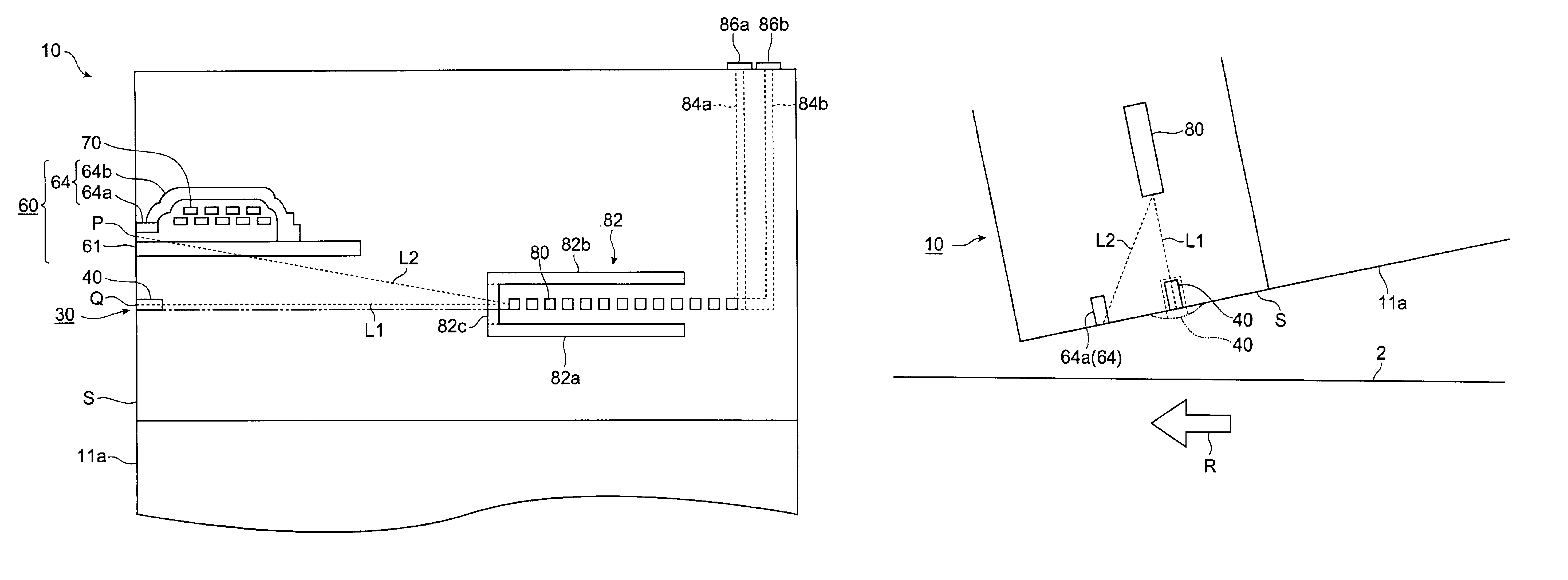
[0020]In the head gimbal assembly and hard disk drive of the present invention, the distance to the heat-generating layer is shorter from the end part on the side facing the recording medium in the magnetoresistive device than from the end part on the side facing the recording medium in the electromagnetic transducer. Therefore, even when the thin-film magnetic head tilts so that its electromagnetic transducer side approaches the recording medium when floating up from the recording medium, the amount of thermal expansion caused by the heat from the heat-generating layer is greater in the magnetoresistive device than in the electromagnetic transducer. This reduces the gap between the magnetoresistive device and the recording medium, whereby a high reproducing output can be obtained.

Problems solved by technology

However, since the thin-film magnetic head tilts forward (in the hard disk rotating direction) when floating up as such, the distance from the hard disk becomes longer to the magnetoresistive device than to the induction type electromagnetic transducer.
Namely, even when the head flying height can be set to a small value, this height is a value obtained in the vicinity of the electromagnetic transducer located near the hard disk, whereas the gap between the magnetoresistive device and the hard disk may not be minimized.
When the distance between the magnetoresistive device and the hard disk is long, a high reproducing output is hard to obtain.

Method used


Image

  • Thin-film merged magnetic head having a heat-generating layer
  • Thin-film merged magnetic head having a heat-generating layer
  • Thin-film merged magnetic head having a heat-generating layer

Examples


Embodiment Construction

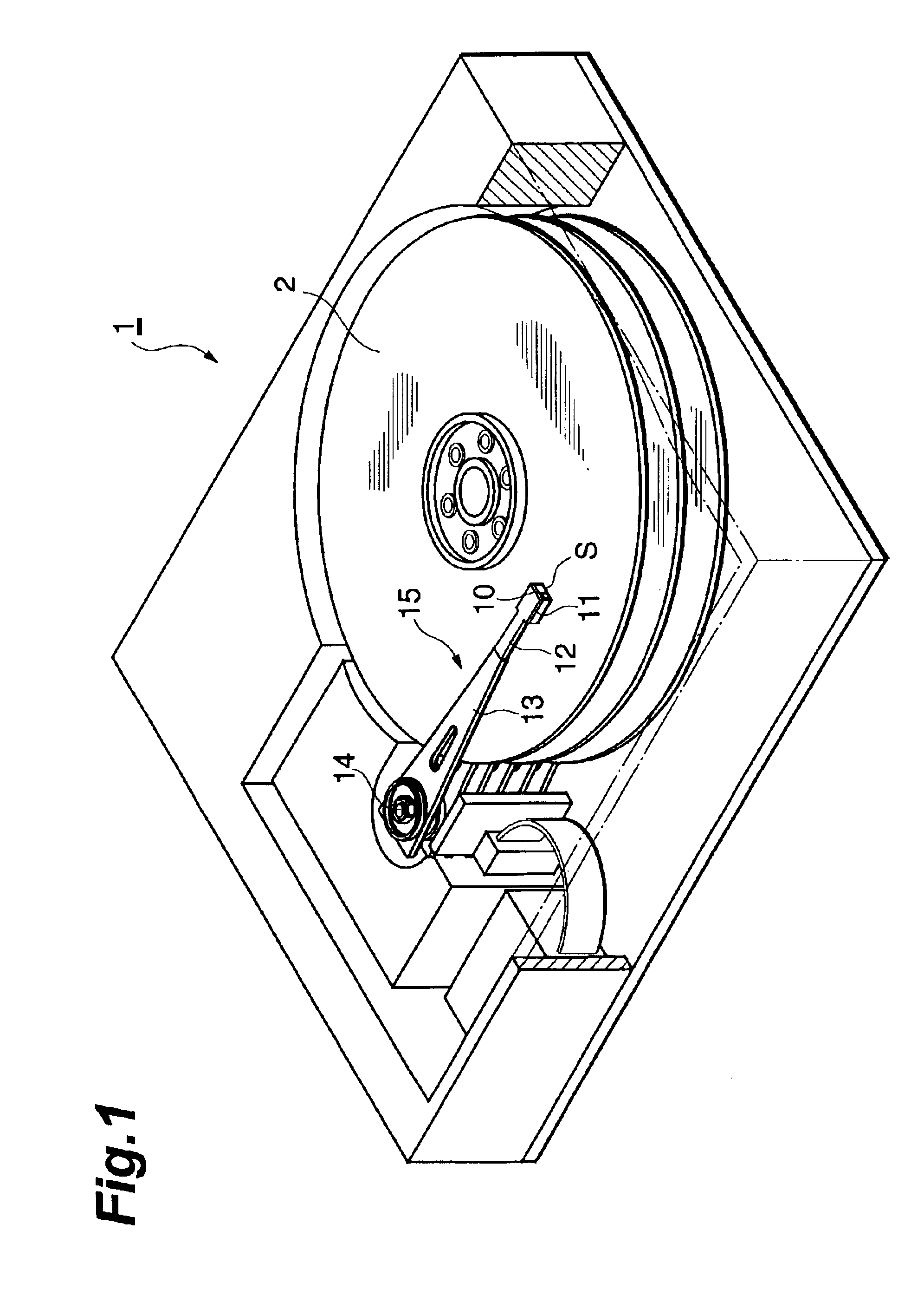
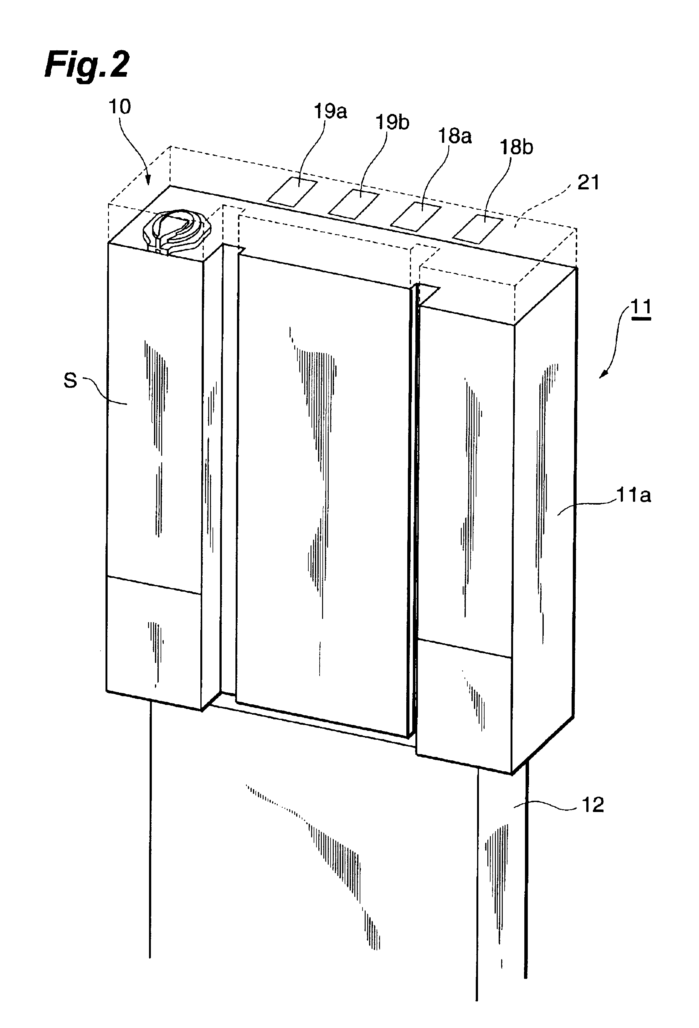
[0033]In the following, preferred embodiments of the thin-film magnetic head, head gimbal assembly, and hard disk drive in accordance with the present invention will be explained in detail with reference to the accompanying drawings. Constituents identical to each other will be referred to with numerals identical to each other, without repeating their overlapping explanations.

[0034]FIG. 1 is a view showing a hard disk drive equipped with a thin-film magnetic head in accordance with an embodiment. This hard disk drive 1 actuates a head gimbal assembly (HGA) 15, so as to cause a thin-film magnetic head 10 to record and reproduce magnetic information with respect to a recording surface (the upper face in FIG. 1) of a hard disk 2 rotating at a high speed. The head gimbal assembly 15 comprises gimbals 12 mounted with a head slider 11 formed with the thin-film magnetic head 10, and a suspension arm 13 connected to the gimbals 12; and is rotatable about a shaft 14 by a voice coil motor, fo...


PUM


Abstract

In the thin-film magnetic head of the present invention, the distance to a heat-generating layer is shorter from the end part on the side facing, a recording medium in a magnetoresistive device than from the end part on the side facing the recording medium in an electromagnetic transducer. Therefore, even when the thin-film magnetic head tilts so that its electromagnetic transducer side approaches the recording medium when floating up from the recording medium, the amount of thermal expansion caused by the heat from the heat-generating layer is greater in the magnetoresistive device than in the electromagnetic transducer. This reduces the gap between the magnetoresistive device and the recording medium, whereby a high reproducing output can be obtained.

Description

BACKGROUND OF THE INVENTION[0001]1. Field of the Invention[0002]The present invention relates to a combination thin-film magnetic head in which a magnetoresistive (MR) device and an induction type electromagnetic transducer are laminated together, a head gimbal assembly, and a hard disk drive.[0003]2. Related Background Art[0004]Thin-film magnetic heads have been configured so as to float up from a hard disk, which is a recording medium, at the time of recording and reproducing with respect to a hard disk drive. Specifically, a thin-film magnetic head is mounted on gimbals, which are attached to a leading end part of a flexible suspension arm, so as to constitute a head gimbal assembly (HGA). As an airflow caused by a rotation of the hard disk runs under the thin-film magnetic head, the suspension arm flexes, whereby the head floats up.[0005]As the hard disk has been attaining a higher density, the gap between the thin-film magnetic head and the hard disk, i.e., head flying height, ...

Claims


Application Information

Patent Timeline
IPC IPC(8): G11B5/012G11B5/39G11B5/31G11B5/00G11B5/54G11B5/58G11B5/48
CPCG11B5/012G11B5/3103G11B5/3133G11B5/3967G11B5/6064G11B5/4886G11B5/54G11B5/581G11B2005/0002
Inventor YAMANAKA, NOBORUOTA, NORIKAZU
Owner TDK CORPARATION
Why Eureka
Eureka Blog
Learn More