Input buffering and queue status-based output control for a digital traffic switch

Inactive Publication Date: 2005-07-19
ALCATEL LUCENT SAS
View PDF19 Cites 7 Cited by
  • Summary
  • Abstract
  • Description
  • Claims
  • Application Information

AI Technical Summary

Benefits of technology

[0013]In its most basic feature, the present invention provides a DIBOC buffer control strategy for a digital traffic sw

Problems solved by technology

Blocking occurs when a cell cannot be delivered because the delivery of other cells is taking up the resources necessary for the delivery of the blocked cell.
Blocking is undesirable, since it can delay the delivery of other cells.
Due to these inevitable delays in delivery, a successful architecture must properly queue cells for delivery to output ports.
Even with buffer control, it is sometimes necessary to “drop” cells.
Such handshaking procedures have several weaknesses.
First, a request must be transmitted to the output side for each cell even though the cell's logical output queue may already have a cell pending, resulting in the transmission of superfluous control t

Method used


Image

  • Input buffering and queue status-based output control for a digital traffic switch
  • Input buffering and queue status-based output control for a digital traffic switch
  • Input buffering and queue status-based output control for a digital traffic switch

Examples


Embodiment Construction

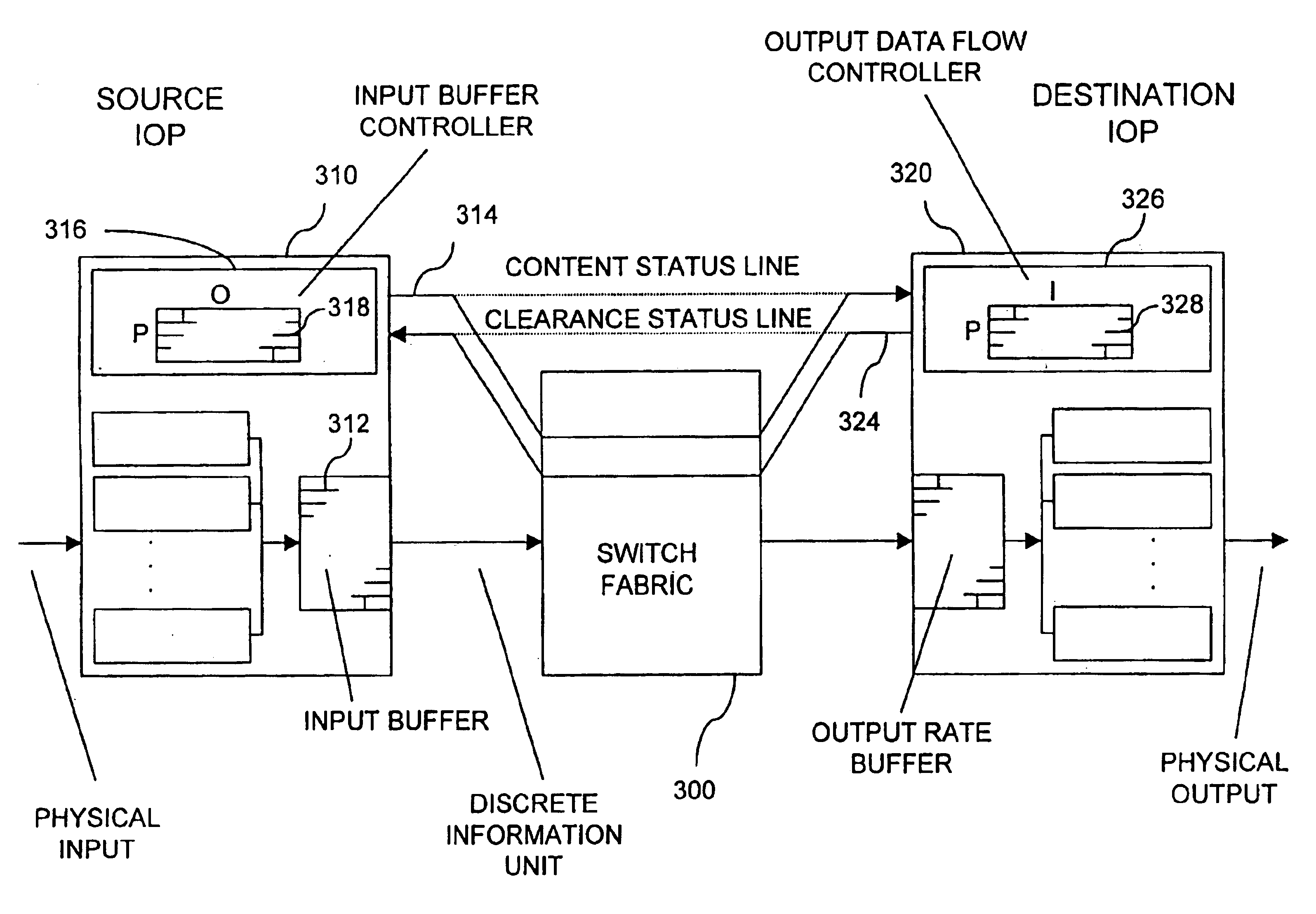
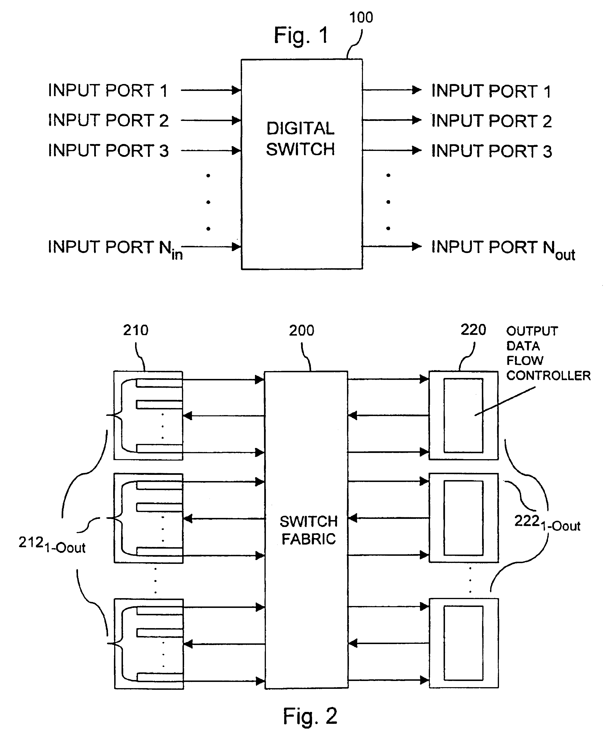
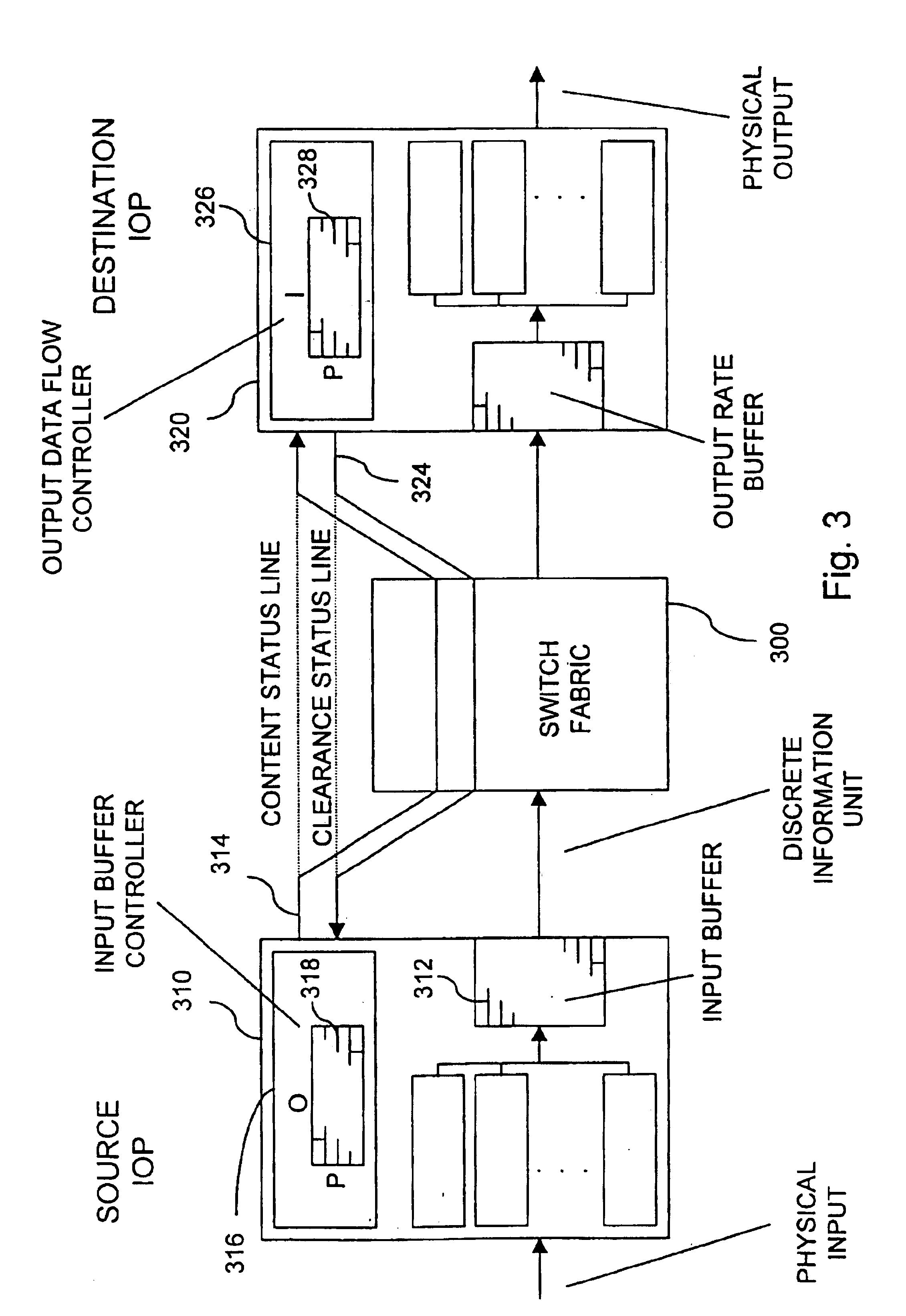
[0024]Referring to FIG. 2, the general architecture of a digital traffic switch incorporating the present invention is shown. Multiple inputs and multiple outputs are coupled via a switch fabric 200 such that every input port (and its associated input buffer control unit) may communicate with every output port (and its associated output data flow control unit), and every output port (and its associated output data flow control unit) may communicate with every input port (and its associated input buffer control unit). At any given instant in time, a subset (or all) of the source input-output processors (IOP) 210 receive digital traffic destined for a subset (or all) of the destination IOP 220. Digital traffic may therefore be imagined as flowing from left to right, from source IOP 210 to destination IOP 220. Each source IOP may have one or more associated input ports and each destination IOP may have one or more associated output ports.

[0025]Within each source IOP 210, there is an in...


PUM


Abstract

A digital traffic switch having DIBOC buffer control has a queue status-based control strategy to limit status traffic on the switch and status buffer requirements. Status messages are transmitted from inputs to outputs when the content status of a logical output queue has changed from “empty” to “not empty”, or vice versa, rather than on a “per cell” request basis. Status messages are transmitted from outputs to inputs when the clearance status of a logical output queue has changed from “not clear to release” to “clear to release”, or vice versa, rather than on a “per cell” grant basis. The status of each logical output queue is monitored at outputs by retaining and updating a single status bit which has a particular binary value when the logical output queue's status is “empty” and the opposite binary value when the logical output queue's status is “not empty”. The status of each logical output queue is monitored at inputs by retaining and updating a single status bit which has a particular binary value when the logical output queue's status is “not clear to release” and the opposite binary value when the logical output queue's status is “clear to release”. Outputs generate (but do not transmit) release grants in a logical order determined by running a grant generation algorithm. Inputs release discrete information units in a logical order determined by running a release algorithm. Status messages for logical output queues are re-transmitted when extra bandwidth is available to remove any inaccurate view of the status of the logical output queues resulting from transmission failures of the original status messages.

Description

CROSS REFERENCE TO RELATED APPLICATION[0001]The present application is a continuation of U.S. application Ser. No. 09 / 052,404, filed Mar. 31, 1998, which is a continuation-in-part of U.S. application Ser. No. 08 / 679,360, filed Jul. 11, 1996, now U.S. Pat. No. 5,768,257, issued on Jun. 16, 1998.BACKGROUND OF THE INVENTION[0002]The present invention relates to digital LAN and WAN traffic switches, particularly asynchronous transfer mode (ATM) switches.[0003]An ATM cell switch takes cells from many sources, and routes them to many destinations. Such a switch may be hardware-based, or hardware- and software-based. The architecture can be generalized as shown in FIG. 1. Cells arrive on input ports 1 to Nin and are switched through a switch fabric 100 to various ones of output ports 1 to Nout.[0004]A cell is a fixed size unit which constitutes a fraction of a larger communication. Cells come in on input ports, and get routed to output ports.[0005]Sometimes, collisions take place between c...

Claims


Application Information

Patent Timeline
IPC IPC(8): H04Q11/04H04L12/56
CPCH04L12/5602H04L49/3081H04Q11/0478H04L2012/5647H04L2012/5681
Inventor WALLNER, JOHN D.HOOGENBOOM, CHRIS L.NISHIMURA, MICHAEL J.WILSON, MICHAEL K.
Owner ALCATEL LUCENT SAS
Why Eureka
Try Eureka