Architecture and addressing scheme for storage interconnect and emerging storage service providers

Active Publication Date: 2005-07-19
CIENA
View PDF5 Cites 36 Cited by
  • Summary
  • Abstract
  • Description
  • Claims
  • Application Information

AI Technical Summary

Benefits of technology

[0021]The present invention comprises network architecture and a scheme to separate and virtualize storage traffic and stored data on a shared infrastructure. Advantages of the scheme include the following: allows several users to use the same network to transport data to/from mass storage devices; allows several users to share the same storage devices as

Problems solved by technology

However, there is considerable expense and inefficiency associated with building and maintaining a private SAN.
This solution can be costly, decrease operational simplification, and have other drawbacks.
However, one drawback of this approach is that no two devices are allowed to have the same address, also, there are no robust security mechanisms today that would completely protect one device from being accessed by any other.
This, however, does not address the problem of sharing the network upstream of (including SAN switched network and carrier access network) the storage device.
Some storage devices also offer internal storage virtualization, but then distribution of the customer data is limited to the capacity of that one storage device.

Method used


Image

  • Architecture and addressing scheme for storage interconnect and emerging storage service providers
  • Architecture and addressing scheme for storage interconnect and emerging storage service providers
  • Architecture and addressing scheme for storage interconnect and emerging storage service providers

Examples


Embodiment Construction

)

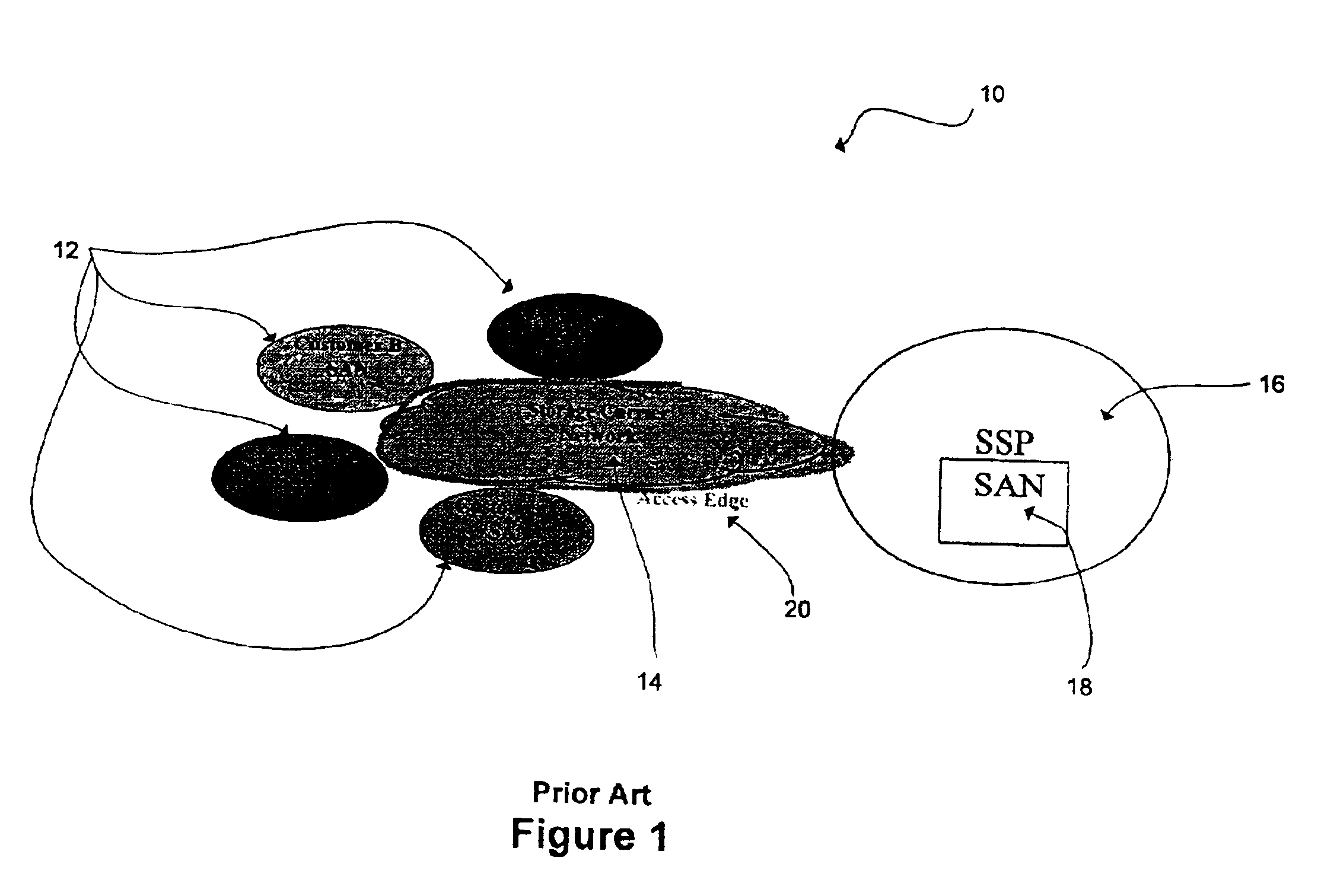
[0035]FIG. 1 is a schematic representation of the basic components of a storage network 10. Each customer has their own SAN 12 connected to a carrier network 14. Also connected to carrier network 14 is SSP 16 with it own SAN 18. In some embodiments, the SSP 16 may also control carrier network 14. Access edge 20 denotes the boundary between customer SAN 12 and carrier network 14.

[0036]As described above, the SSP 16 provides storage space in SAN 18 to one or more customers (e.g., customers A, B, C, in FIG. 1). The customers access the storage space in SAN 18 via carrier network 14. The customers may also link two or more of their own SANs 12 via carrier network 14.

[0037]In general, a SAN (e.g., customer SAN 12 or SSP SAN 18) is composed of mass storage devices connected by equipment to various processor based devices. In some embodiments, a customer may implement a degenerate SAN where there is no storage and a single connection between a processor based device and the carrier networ...


PUM


Abstract

A technique for enabling a shared storage provider (SSP) to provide shared data storage to a plurality of customers while providing greater privacy and security of each customer's data by implementing a virtual private (VP) addressing scheme is disclosed. The technique also allows a storage networking service carrier to provide connectivity between a plurality of customer storage networking sites, keeping each customer separate from each other. In one embodiment, the technique is realized by network architecture and a scheme to separate and virtualize storage traffic and stored data on a shared infrastructure. Functionally, the scheme provides for the following features: translation between user storage network addresses to carrier addresses; recovery of user storage network addresses when data is returned to the user; use of the carrier assigned addresses to separate the users within the carrier's network; recognition of user storage address within the storage device for partitioning within the user's storage space assigned by the SSP; Storage virtualization or the logical representation of a storage independently of its physical organization; and the displacement of address mapping and virtualization functions away from devices directly attached to storage. All of the above can be implemented singly or in combination, by any networking technology including SONET, ATM, IP, Ethernet and Fiber Channel network technologies.

Description

CROSS-REFERENCE TO RELATED APPLICATIONS[0001]This patent application claims priority to U.S. Provisional Patent Application No. 60 / 218,970, filed Jul. 17, 2000 and U.S. Provisional Patent Application No. 60 / 223,911, filed Aug. 9, 2000, which are hereby incorporated by reference herein in their entirety.FIELD OF THE INVENTION[0002]The present invention relates generally to addressing and managing data between interconnected storage area networks (SANs). In particular, to a technique for enabling a storage service provider (SSP) to provide shared data storage to a plurality of customers while ensuring the privacy and security of each customer's data by implementing a virtual private (VP) addressing scheme.BACKGROUND OF THE INVENTION[0003]Under the present mode of operation, many enterprises build and administer private SANs to store their digital information. Typically, the SAN is isolated from outside access to ensure that the stored information remains private. However, there is con...

Claims


Application Information

Patent Timeline
IPC IPC(8): H04L29/06H04L29/08H04L29/12
CPCH04L29/06H04L29/12009H04L29/12018H04L61/10H04L67/1097H04L69/329H04L61/00H04L9/40
Inventor ELLIS, DONALD R.CAWTHORNE, DONFRANK, SILVO J.DEMARGERIE, SYLVAINMURTON, CHRISROMAGNINO, SILVANAWALLACE, R. BRUCE
Owner CIENA
Why Eureka
Try Eureka