Distributed block frequency converter

a frequency converter and distribution block technology, applied in the field of channelized communication systems, can solve the problems of bandwidth limitation, two synthesizers, and the need for bandwidth, and achieve the effects of reducing the number of synthesizers used, reducing the physical size and power requirements, and reducing interference between the resultant rf signals

Inactive Publication Date: 2005-07-19
INCEPTIA +1
View PDF1 Cites 32 Cited by
  • Summary
  • Abstract
  • Description
  • Claims
  • Application Information

AI Technical Summary

Benefits of technology

[0013]It is appreciated that the present invention enables a significant reduction in the number of up-converter synthesizers necessary at the front end of the converter since each synthesizer is used to up-convert a block of channel signals. A single up-converter LO signal may be used by all of the up-converter mixers, or a separate up-converter synthesizer is provided for each up-converter mixer. In either case, the number of up-converter synthesizers is reduced to less than one per channel. In a similar manner, the number of down-converter synthesizers is reduced to less than one per channel. The down-converter LO signals may be separated at least by a predetermined frequency value to reduce interference between the RF signals. To achieve frequency agility, however, the down-converter synthesizers may be adjustable, such as by using tunable oscillators or the like, so that each RF signal may be positioned to an available frequency range within the overall frequency spectrum.
[0014]In one embodiment, the channel signals are modulated by an appropriate modulator, such as according to quadrature amplitude modulation (QAM) or Frequency Shift Keying (FSK) or Quadrature Phase-Shift Keying (QPSK) or the like. Modulation and signal combining may be performed using digital signals, where the combined digital signals are converted to analog format prior to mixing. The channel signals provided to each combiner are separated in frequency to avoid interference with each other. Each combiner, however, may advantageously use the same or similar frequency levels or values so that the combined channel signals are each centered at approximately the same frequency level and may further have approximately the same frequency width prior to up-conversion. In this configuration, the use of the same up-converter LO signal results in each IF signal having approximately the same center frequency and range. In this manner, the bandpass filter arrangement is simplified since each filter is substantially identical. In a particular embodiment, for example, the IF signals may be centered at a convenient frequency level, such as a predetermined global system for mobile communications (GSM) frequency within the 900 MHz frequency range, such as any selected GSM frequency between 800-1000 MHz. In this manner, readily available off-the-shelf GSM bandpass filters may be used. In one particularly efficient configuration, each combiner combines four 6 MHz channels into combined channel signals and IF signals with a bandwidth of 24 MHz, and the up-converter mixers center the IF signals at the same center point of the GSM filters, where each GSM filter has a conventional bandwidth of approximately 25 MHz.
[0017]The method may further include generating multiple up-converter LO signals, so that each combined channel signal is mixed with a corresponding up-converter LO signal. The method may further include separating each channel signal of each subset of channel signals in frequency by a predetermined frequency value. The combining of subsets may include centering each combined channel signals at approximately the same frequency value. The method may further include adjusting the frequency of each down-converter LO signal to locate each of the RF signals within an available frequency range. The adjusting may include adjusting the frequency of each down-converter LO signal to reduce interference between the resultant RF signals. The method may further include modulating each of the plurality of channel signals prior to combining.
[0018]It is appreciated that block conversion of multiple channels in a channelized communication system enables a substantial reduction in the number of synthesizers used in the converter circuitry. A reduced number of synthesizers results in a significant reduction in the physical size and power requirements of the converter circuitry, thereby achieving a more efficient design of the communication system equipment.

Problems solved by technology

Most applications, including those associated with the cable television industry, are bandwidth-limited in that the available frequency spectrum is not constant across the industry.
At least one problem with the typical dual up-conversion and down-conversion process is that two synthesizers are necessary for each channel.
Each synthesizer consumes a substantial amount of both space and power.
If a significant number of channels are necessary, the physical size and power requirements becomes relatively excessive due in large part to the synthesizer circuits alone.
Nonetheless, such circuits are still subject to existing physical limits so that equipment designed to handle a significant number of channels is physically large and requires a substantial amount of power.
The existing legacy technology for providing broadband content is becoming increasingly inadequate to meet the demand.
The quality of service is particularly low during popular usage time periods.
The resulting upstream performance is often no better (and sometimes less) than a standard 56 Kbps modem.

Method used


Image

  • Distributed block frequency converter
  • Distributed block frequency converter
  • Distributed block frequency converter

Examples


Embodiment Construction

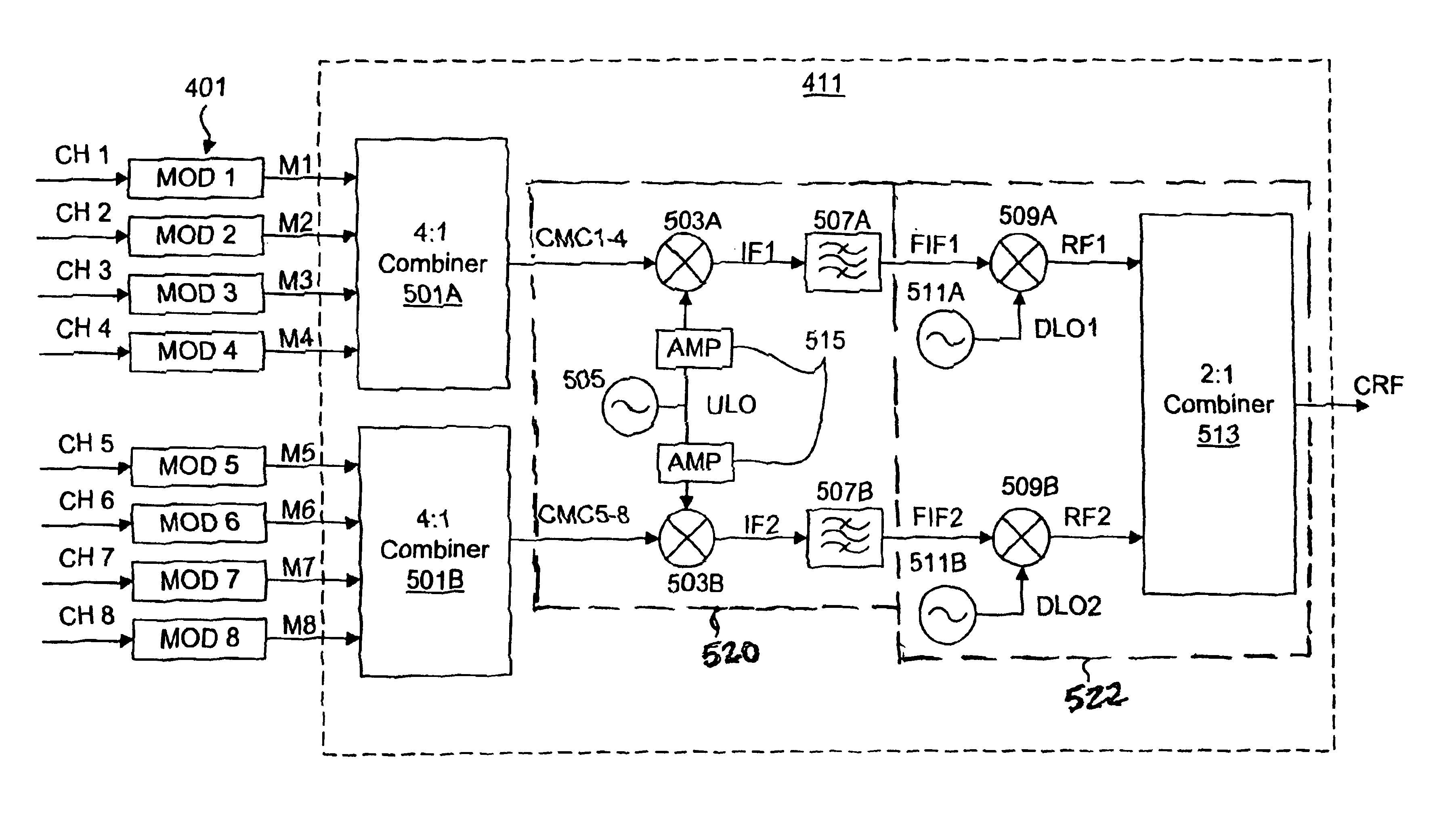
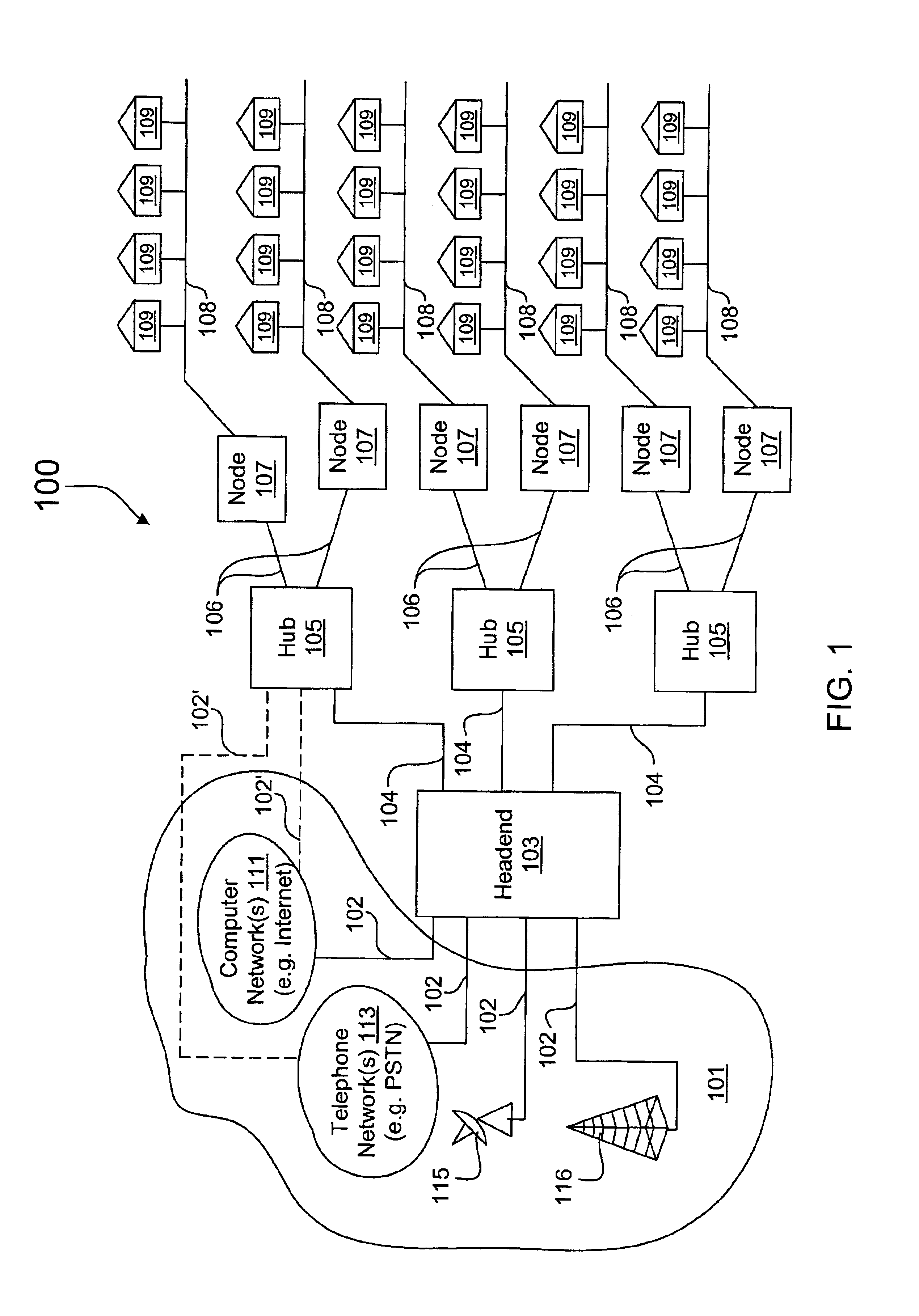
[0026]FIG. 1 is a block diagram of an exemplary communication system 100 with an exemplary network architecture used to illustrate principles of the present invention. One or more sources 101 are coupled via appropriate communication links 102 to deliver source information to a headend 103, which distributes the source information to one or more distribution hubs 105 via respective communication links 104. Each distribution hub 105 further distributes source information to one or more nodes 107 via communication links 106, where each node 107 in turn distributes the source information to one or more subscriber locations 109 via subscriber links 108. In the embodiment shown, bi-directional communication is supported in which upstream subscriber information from any one or more of the subscriber locations 109 is delivered to the corresponding distribution hub 105 via the corresponding subscriber links 108. Depending upon the nature of the subscriber information and the network archite...


PUM


Abstract

A distributed block frequency converter that combines multiple channel signals into a combined radio frequency (RF) signal suitable for transport via selected media. The converter includes combiners that each combine at least two channel signals into a combined channel signal, an up-converter synthesizer that generates an up-converter local oscillator (LO) signal, up-converter mixers that each mix a combined channel signal with the up-converter LO signal to provide a corresponding intermediate frequency (IF) signal, bandpass filters that each filter an IF signal, down-converter synthesizers, down-converter mixers that each mix a down-converter LO signal with a corresponding filtered signal to provide a corresponding RF signal, and an RF combiner that combines the RF signals into a single RF signal. The down-converter synthesizers are adjustable to achieve frequency agility on a block by block basis.

Description

CROSS-REFERENCE TO RELATED APPLICATION(S)[0001]The present application is related to U.S. Application entitled “TIME DIVISION MULTIPLEXING OVER BROADBAND MODULATION METHOD AND APPARATUS”, application Ser. No. 09 / 804,104 filed Mar. 12, 2001, which is hereby incorporated by reference in its entirety.FIELD OF THE INVENTION[0002]The present invention relates to channelized communication systems, and more particularly, to a distributed block frequency converter that combines and up-converts multiple channels for transport via selected media.DESCRIPTION OF RELATED ART[0003]Channelized communication systems often require that multiple channel signals or bands be combined into a common or single signal for transporting via a selected medium, such as the air (wireless) or a selected media, such as electrical or optical cables. In general, an up-conversion processes is performed to combine the signals at a higher frequency carrier signal or the like with sufficient bandwidth to carry the comb...

Claims


Application Information

Patent Timeline
Patent Type & Authority Patents(United States)
IPC IPC(8): H04J1/06H04L5/02H04N7/22H04J1/00H04N7/10H04L5/06H04Q7/30H04N7/52H04J14/02H04N21/2365H04N21/2383H04W88/08
CPCH04B1/0003H04J1/065H04L5/06H04N7/102H04N7/22H04N7/52H04N21/2365H04N21/2383H04W88/085H04J14/0298
Inventor HINSON, SCOTT R.
Owner INCEPTIA
Why Eureka
Try Eureka