Building system

a building system and building technology, applied in the direction of girders, roofs, transportation and packaging, etc., can solve the problems of cost and unfavorable space planning of less than 16 inches (40 cm), and achieve the effect of safe installation and less detrimental environmental impa

Inactive Publication Date: 2005-07-26
ADV TECH BUILDING SYST
View PDF49 Cites 39 Cited by
  • Summary
  • Abstract
  • Description
  • Claims
  • Application Information

AI Technical Summary

Benefits of technology

[0008]A structure using a floor system of the present invention can be safely installed onto a perimeter supporting structure, whether that structure constitutes a perimeter foundation, basement wall, or other support, without the need for any piers that are typically used to support the longitudinal beams of conventional modular construction. Of course, one or more piers or a girder may be required at a marriage line of two structures of the present invention when placed side by side. Further, once the floor system of the present invention is positioned on the perimeter foundation,

Problems solved by technology

It will be appreciated that there is no real minimum spacing between members having a stiffness equal to the required secondary stif

Method used


Image

  • Building system
  • Building system
  • Building system

Examples


Embodiment Construction

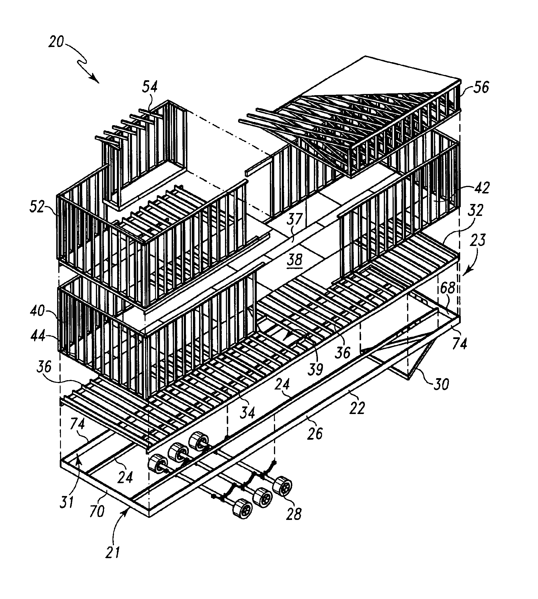
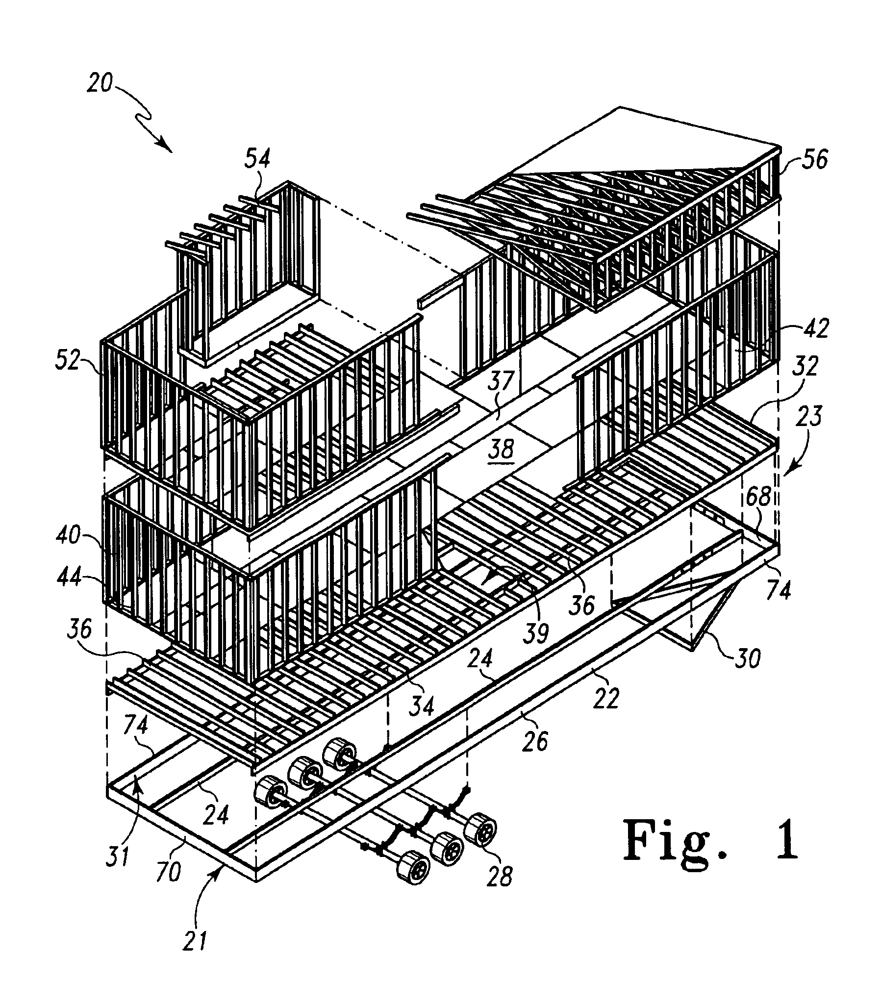
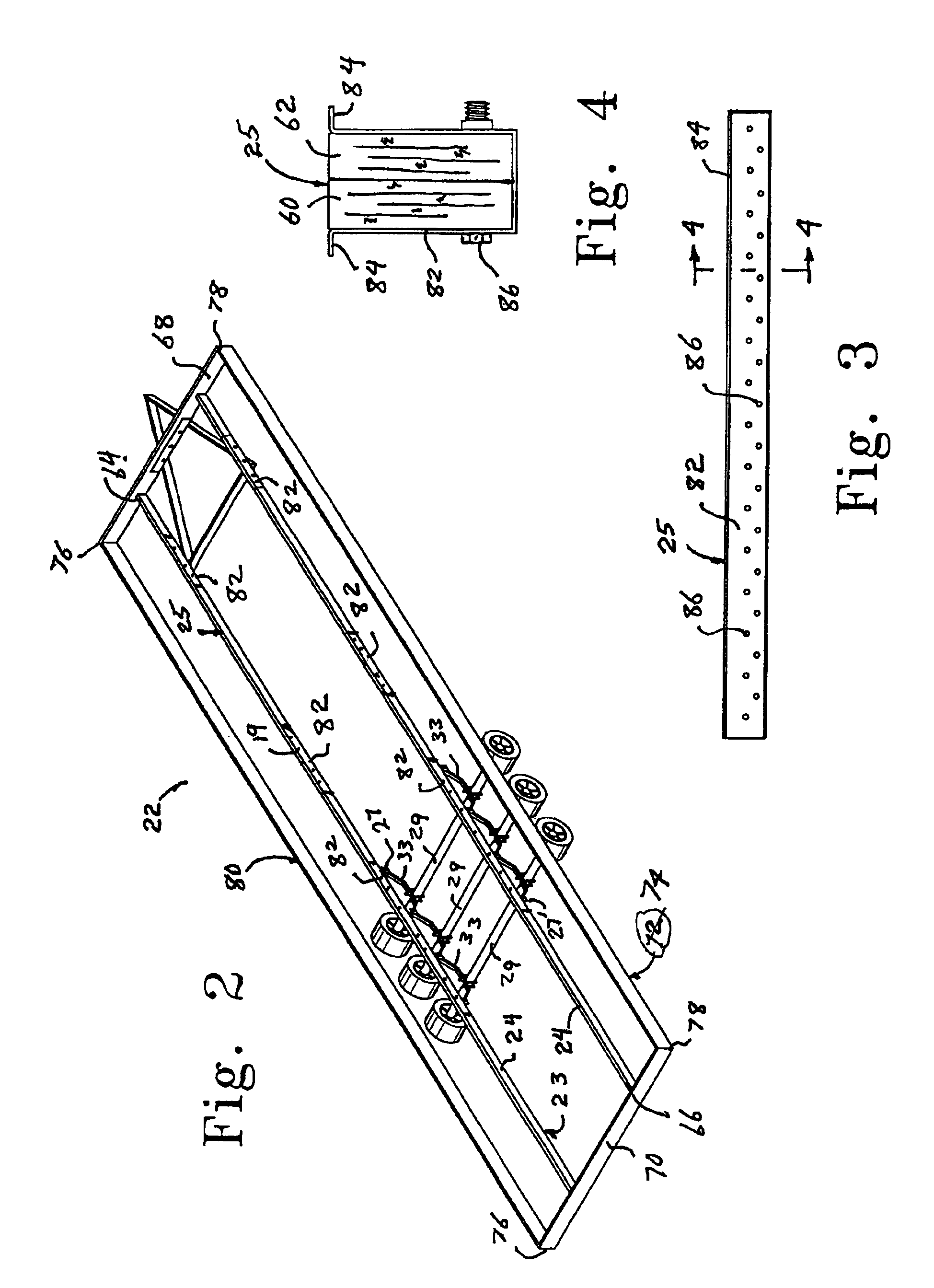
[0032]An off-site factory built structure 20 in accordance with the present invention is shown in an exploded perspective view in FIG. 1. The structure 20 includes a chassis 22 having of a pair of parallel interior longitudinal beam members 24. A rectangular perimeter 26 is coupled to the ends of the longitudinal beam members 24. The rectangular perimeter 26 is defined by a pair of lateral perimeter members 68 and 70 coupled to the ends of the longitudinal beam members 24. The lateral perimeter members 68 and 70 include ends joined to ends of two longitudinal perimeter members 74. A running gear 28 is coupled to the bottom of the interior longitudinal beam members 24 near a rearward end 21 of the chassis 22. A tow member 30 is coupled to a forward end 23 of the chassis 22. Further details of the chassis 22 are provided in the subsequent description of FIGS. 2-8.

[0033]A floor system 32 is shown in the exploded view of FIG. 1 elevated above the chassis 22. It will be appreciated that ...


PUM


Abstract

Off-site factory built structure employs a chassis including two interior longitudinal beam members joined at their ends to a perimeter structure. A floor system is integrated within the chassis perimeter. A ledger member is fixed to the inner surface of each longitudinal perimeter member so that a top surface lies in a plane coincident with top surfaces of the interior longitudinal beams. Lateral members are coupled to the tops of the interior longitudinal beams and to the top of the ledger members. The lateral members include secondary stiffening members such as C-channel members, metal Z-channel members, or other metal members of similar structural capacity, spaced apart from each other by a maximum distance S, related to the width of the floor system W, by the equation:
S 12−½W.

Description

CROSS-REFERENCE TO RELATED APPLICATION[0001]This application is related to, and claims all available rights and benefits of, U.S. Provisional Application Ser. No. 60 / 386,303 filed Jun. 5, 2002.BACKGROUND OF THE INVENTION[0002]The present invention is directed to a building system especially useful in off-site, factory built structures including manufactured and modular constructions as well as in recreational vehicles, panelized housing and other buildings that are transportable from the manufacturing location to a final site of more or less fixed location. The present invention is particularly directed to a chassis system to be employed in the construction and transport of the structure. The invention is also directed to a floor system to be used in cooperation with the chassis that provides important advantages. The invention is also directed to an integrated lifting system for the structure so that the structure can be installed easier, safer, with less labor, and with less oppor...

Claims


Application Information

Patent Timeline
IPC IPC(8): B62D21/18B62D21/20E04B1/343
CPCB62D21/20E04B1/34336
Inventor JOHNS, EVOR F.ROSE, JAMES E.EPPERSON, SKYLER J.PULVER, MARC H.LONG, KENNETH A.
Owner ADV TECH BUILDING SYST
Why Eureka
Try Eureka