Engine cooling disc valve

a technology of engine cooling disc and valve body, which is applied in the direction of machines/engines, mechanical equipment, cylinders, etc., can solve the problems of reducing the service life of the engin

Inactive Publication Date: 2005-07-26
VISTEON GLOBAL TECH INC
View PDF21 Cites 34 Cited by
  • Summary
  • Abstract
  • Description
  • Claims
  • Application Information

AI Technical Summary

Problems solved by technology

Furthermore, delays in warming up of the engine also delay the availability of heat in the passenger compartment.
Achieving these additional functions becomes expensive not only because of the proliferation of valves, but also because of the proliferation of separate actuators and wiring, cables, or hydraulic or pneumatic (e.g. vacuum) lines required to control them.
The addition of the clutch either interior or exterior to the actuator adds more components, which adds to the expense, and requires additional packaging space.

Method used


Image

  • Engine cooling disc valve
  • Engine cooling disc valve
  • Engine cooling disc valve

Examples


first embodiment

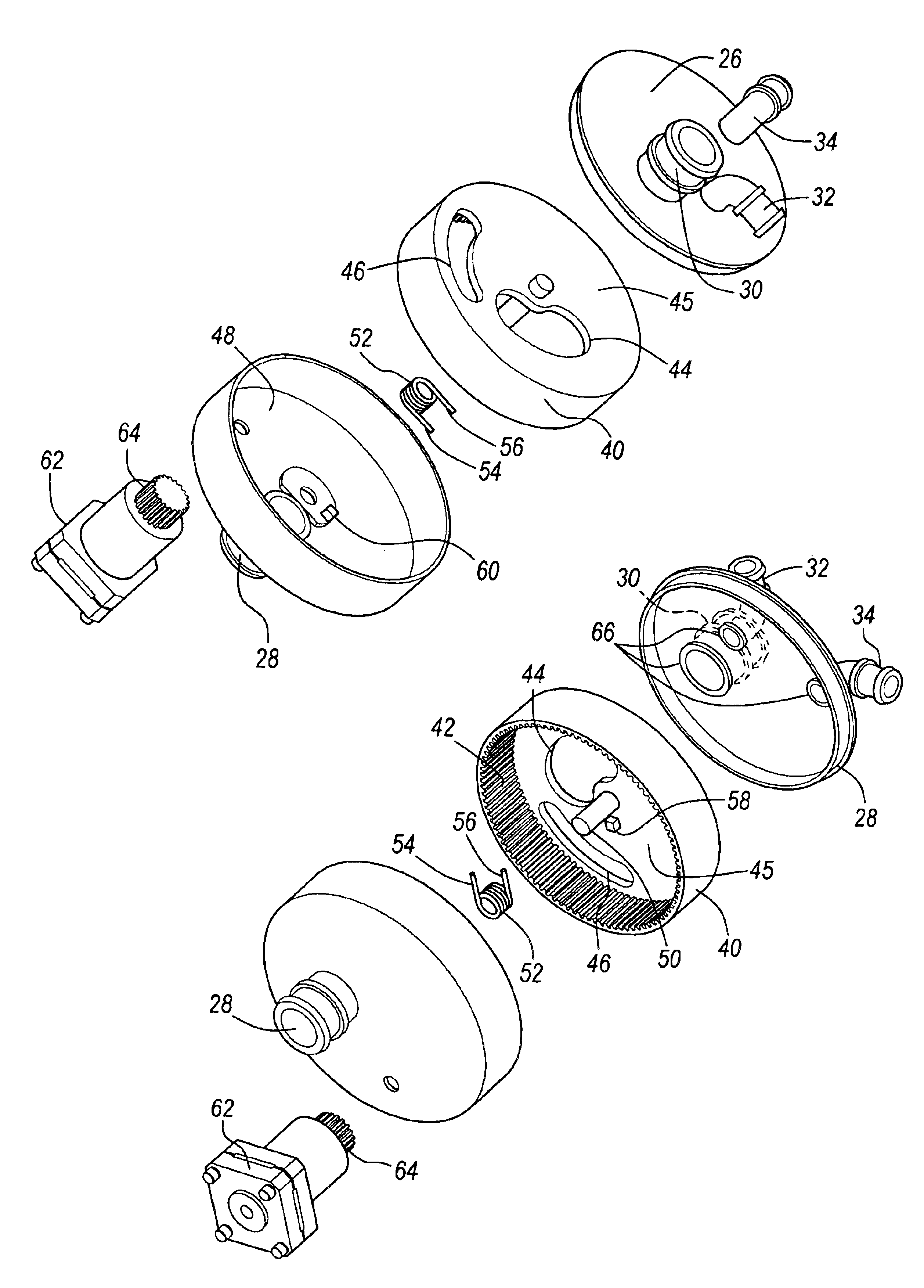
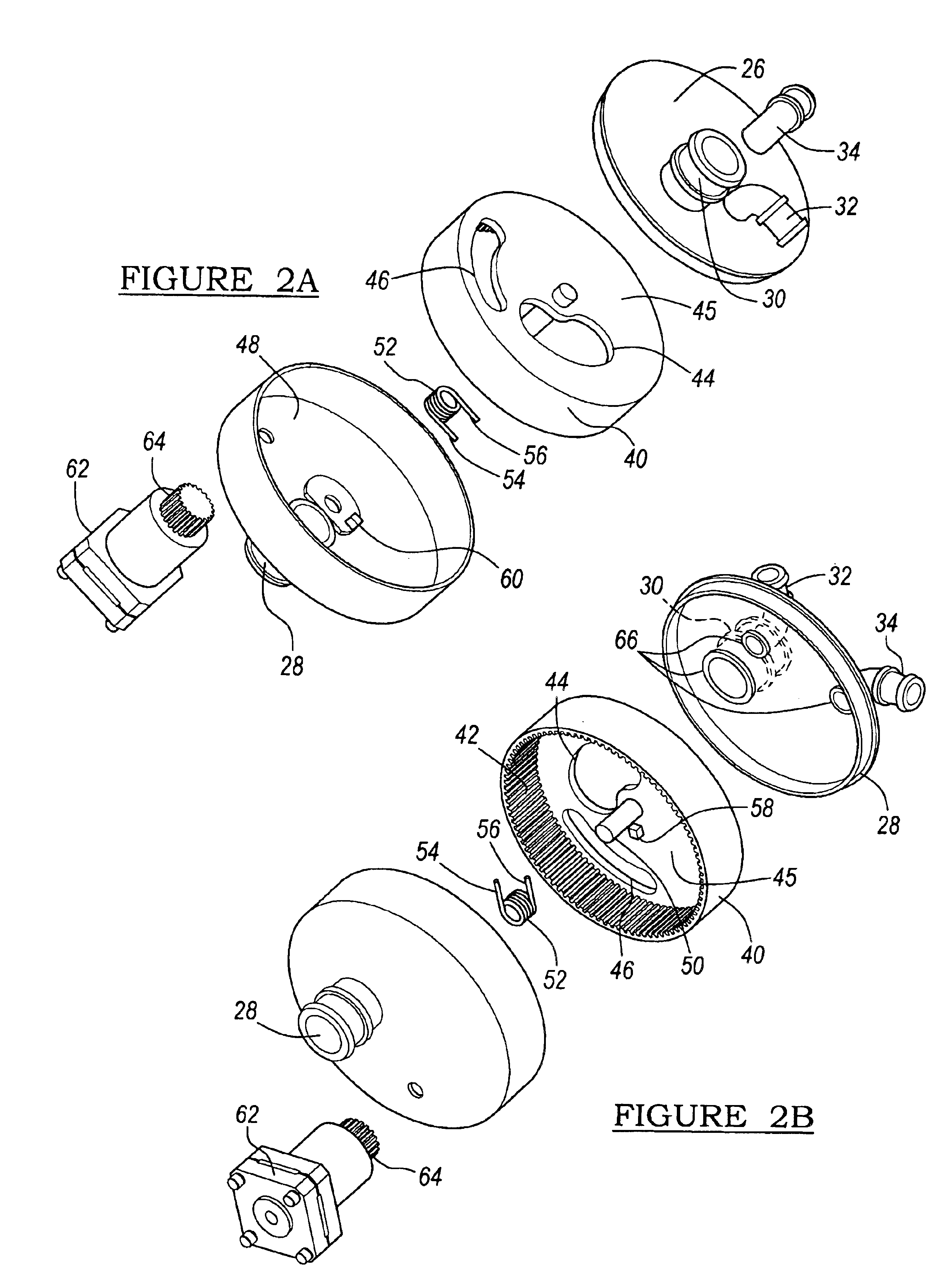
[0028]FIG. 2a illustrates the rotary valve 10 comprising a valve body 26 The valve body 26 comprises at least three outlet ports in the preferred embodiment. The outlet ports include a radiator port 30, a heater port 32, and an auxiliary port 34. The auxiliary port 34 may either be an oil-cooler port as in the diesel application or a bypass port as in the gasoline application. The valve body 26 is cylindrical shaped and the outlet ports are positioned on the top surface of the valve body 26. The radiator port 30 and the heater port 32 are positioned at a first radius on the valve body 26 whereas the auxiliary port 34 is positioned at a second radius on the valve body 26. An internal gear driven rotary disc 40 is positioned below the valve body 26. A gear driven mechanism 42 (shown in FIG. 2b) is located about an entire inner circumference and on the underside of the rotary disc 40 and integrally molded with the rotary disc 40, although the gear driven mechanism 42 may also be a sepa...

second embodiment

[0036]FIG. 7a illustrates a top view of the rotary disc 40 of a gasoline application according to a In this the auxiliary port 34 functions as the bypass port. A small circumferential length is incorporated in the second aperture 46 because the engine 13 needs non-cooled coolant only during a short interval while the vehicle is operating such as when a vehicle is initially started and it is desirable to bring engine temperatures quickly up to a desired operating temperature range. FIG. 7b shows flow rates for the rotary disc 40 as shown in FIG. 7a.

[0037]As a result of the forgoing interactions between the rotary disc and the ports, the rotary valve is able to adapt to diesel or gasoline applications with just minor modification to the circumferential length and positioning of the apertures. The same radius for each of the ports for both diesel and gasoline applications may be applied. Various engine sizes and cooling systems can be accommodated by making minor and low cost modific...


PUM


Abstract

A multi-port rotary valve used to distribute coolant to an engine cooling system comprises a valve body having a plurality of outlet ports for directing coolant flow to a radiator circuit, a heater circuit, and an auxiliary circuit. An internal gear driven rotary disc includes a gear driven mechanism located on an inner circumference of the rotary disc. The rotary disc includes two apertures positioned on a top surface of the rotary disc for regulating predetermined flow paths and flow rates to the plurality of ports. An inlet housing body which includes an inlet port mates with the valve body and encases the rotary disc. An actuator which is coupled to a drive gear mounted internal to the inlet housing body is responsive to a control signal for transmitting a torque to the internal drive gear for rotating the rotary disc to regulate coolant flow.

Description

CROSS REFERENCE TO RELATED APPLICATIONS[0001]Not Applicable.STATEMENT REGARDING FEDERALLY SPONSORED RESEARCH[0002]Not Applicable.BACKGROUND OF THE INVENTION[0003]1. Field of the Invention[0004]The present invention relates in general to automotive engine cooling systems, and, more specifically, to a multi-port valve for distributing and controlling coolant flow to cooling system circuits.[0005]2. Description of the Related Art[0006]Conventional cooling systems for internal combustion engines include a coolant circuit within an engine block, a radiator, a fan, a heater core, water pump, and various hoses and clamps. They also include a thermostat and / or various valves to control the flow of coolant in response to the temperature of the coolant, demand for heating of the passenger compartment, and other factors.[0007]When an engine is first warming up after being started, it is known to have the coolant flow bypass the radiator so that the coolant and the engine warm up more quickly. ...

Claims


Application Information

Patent Timeline
Patent Type & Authority Patents(United States)
IPC IPC(8): F01P7/16F01P7/14
CPCF01P7/167F16K11/074F01P2007/146F01P2023/00F01P2023/08F01P2031/32F01P2060/04F01P2060/08
Inventor LELKES, MARKLENGYEL, PETERLOU, ZHENG
Owner VISTEON GLOBAL TECH INC
Why Eureka
Try Eureka