Joint for use with expandable tubulars

a technology for expanding tubulars and joints, which is applied in the direction of drilling pipes, drilling casings, borehole/well accessories, etc., can solve the problems of other operations that fail to accommodate a length change in an expandable tubular, the tubular is compressed, and the tubular is strained, so as to eliminate the tension or compression force

Inactive Publication Date: 2005-07-26
WEATHERFORD TECH HLDG LLC
View PDF19 Cites 33 Cited by
  • Summary
  • Abstract
  • Description
  • Claims
  • Application Information

AI Technical Summary

Benefits of technology

[0014]Further, a method for substantially eliminating tension or compression forces within an expandable tubular string positioned in a wellbore is provided. The method includes inserting at least one connection assembly in the expandable tubular string. The connection assembly comprising a first expandable tubular connected in a telescopic relation to a second expandable tubular and a releasable connection for selectively permitting axial movement, between the first expandable tubular and the second expandable tubular. The method further includes running the expandable tubular string into the wellbore and releasing the releasable connection by a predetermined axial force created while expanding radially at least a portion of the expandable tubular string. The method also includes sliding the first expandable tubular axially within the second expandable tubular to substantially eliminate the tension or compression forces.

Problems solved by technology

This change in length of the tubular can cause compression of the tubular and present problems in certain instances.
The similar problem occurs when radially expanding from the bottom up while a top of the tubular string is anchored to casing or liner or necessarily held in place with a run-in tool.
This change in length of the tubular can cause tension within the tubular in certain instances.
These examples represent possible problems due to elongation and contraction of tubulars in a wellbore during expansion.
However, other operations are envisioned that also fail to accommodate a length change in an expandable tubular as a result of the radial expansion thereof.

Method used


Image

  • Joint for use with expandable tubulars
  • Joint for use with expandable tubulars
  • Joint for use with expandable tubulars

Examples


Embodiment Construction

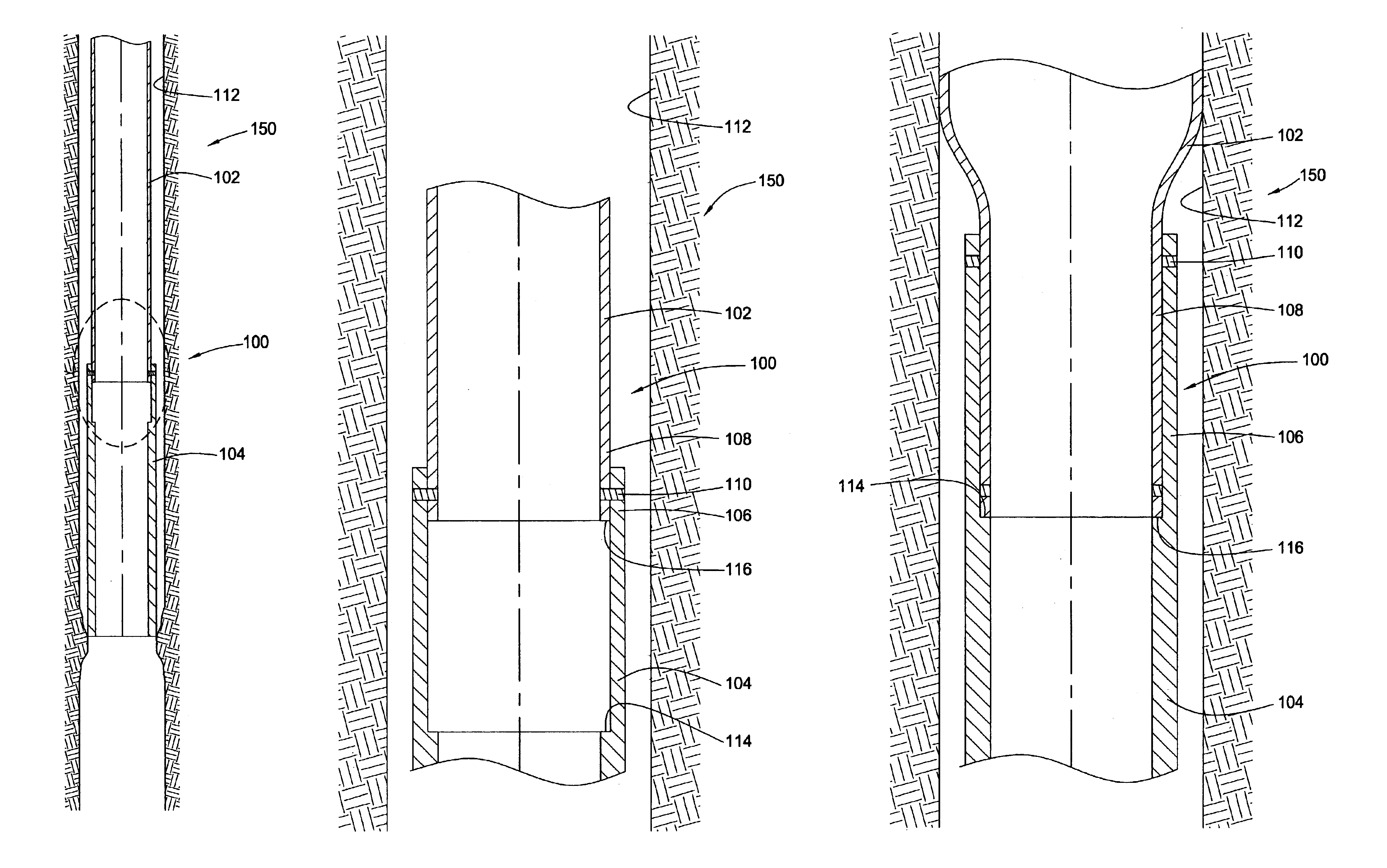
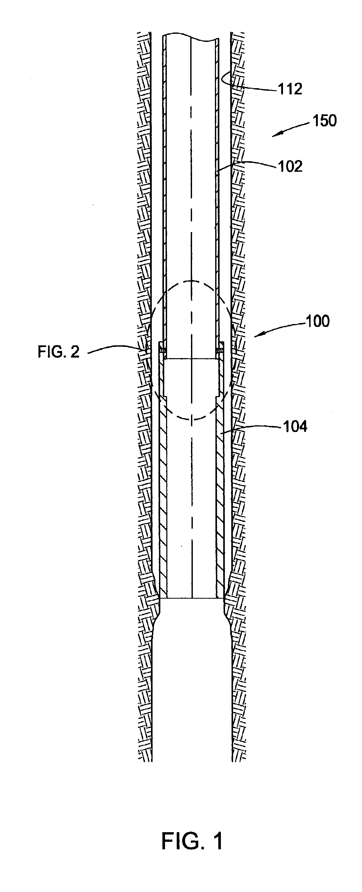
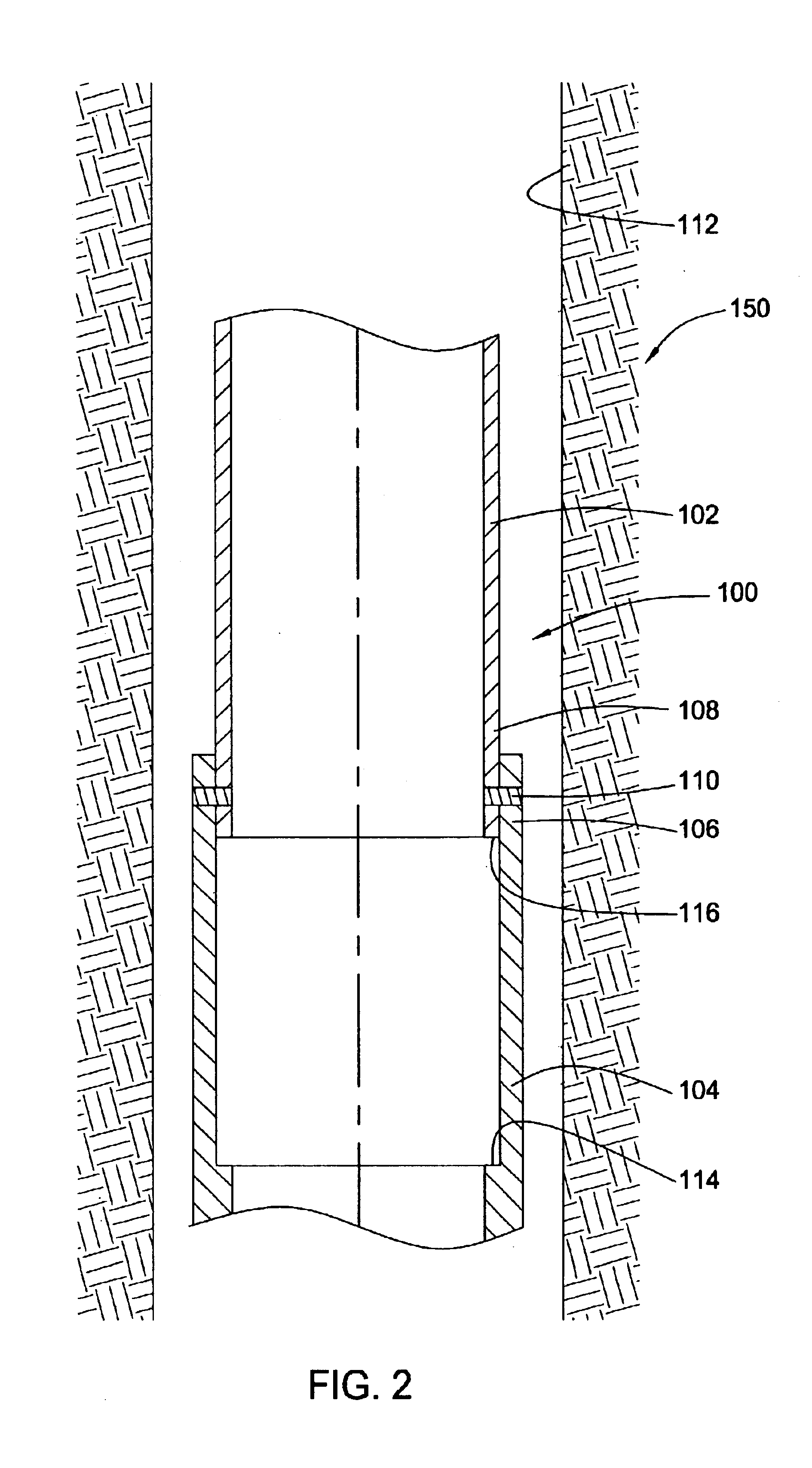
[0019]Embodiments of the present invention generally relate to a method and an apparatus for connecting a first expandable tubular and a second expandable tubular using a joint that selectively permits axial movement between the tubulars in response to contraction or elongation of the tubulars due to their radial expansion.

[0020]FIG. 1 is a cross-sectional view illustrating a string of expandable tubulars 150 disposed in a wellbore 112 and showing one embodiment of the joint 100 of the present invention. Generally, a running assembly (not shown) connected to an upper end of the string of expandable tubulars 150 is used to place the string of expandable tubulars 150 in the wellbore 112. The string of expandable tubulars 150 is typically lowered to a predetermined point or until it contacts a restriction in the wellbore as illustrated in FIG. 1. In either case, the upper portion of the string of expandable tubulars 150 is secured in the wellbore 112 by an anchor (not shown) or by othe...


PUM


Abstract

Embodiments of the present invention generally relate to a joint used with expandable sand screens and other expandable tubulars that permits elongation or contraction of the expandable tubulars during a tubular expansion operation within a wellbore. In one aspect, a connection assembly for use with expandable tubulars is provided. The connection assembly includes a first expandable tubular axially fixable at one end within a wellbore and a second expandable tubular axially fixable at one end within the wellbore. The second expandable tubular has an opposite end adapted to receive an opposite end of the first expandable tubular to provide a joint between the tubulars. The connection assembly further includes a releasable connection between the opposite ends of the tubulars for selectively permitting axial movement of the opposite ends relative to each other. In another aspect, a method for joining a first expandable tubular and a second expandable tubular is provided. Furthermore, a method for substantially eliminating tension or compression forces within an expandable tubular string positioned in a wellbore is provided.

Description

BACKGROUND OF THE INVENTION[0001]1. Field of the Invention[0002]The present invention relates to expandable sand screens and other expandable tubulars. More particularly, the present invention relates to a joint used with expandable sand screens and other expandable tubulars that permits elongation or contraction of the expandable tubulars during a tubular expansion operation within a wellbore.[0003]2. Description of Related Art[0004]Hydrocarbon and other wells are completed by forming a borehole in the earth and then lining the borehole with steel pipe or casing to form a wellbore. After drilling a section of the wellbore, a string of casing is lowered into the wellbore and temporarily hung therein from the surface of the well. Using apparatus known in the art, the casing is cemented into the wellbore by circulating cement into the annular area defined between the outer wall of the casing and the borehole. The combination of cement and casing strengthens the wellbore and facilitate...

Claims


Application Information

Patent Timeline
Patent Type & Authority Patents(United States)
IPC IPC(8): E21B17/07E21B17/02E21B43/10E21B43/02
CPCE21B17/07E21B43/103E21B43/106
Inventor ZIMMERMAN, PATRICK J.
Owner WEATHERFORD TECH HLDG LLC
Why Eureka
Try Eureka