Walk-behind electric cultivating machine

a technology of electric soil cultivating machine and electric motor, which is applied in the direction of tilling equipment, agriculture tools and machines, agriculture, etc., can solve the problems of increased burden on the human operator, poor cultivating finish, insufficient cultivating performance, etc., to reduce the possibility of unfavorable cultivation, enhance the linear traveling capability and operability of the machine, and limit the effect of unfavorable cultivation

Inactive Publication Date: 2005-07-26
HONDA MOTOR CO LTD
View PDF17 Cites 9 Cited by
  • Summary
  • Abstract
  • Description
  • Claims
  • Application Information

AI Technical Summary

Benefits of technology

[0013]With the transmission mechanism positioned immediately below the motor rotation shaft extending downward and the batteries positioned around and adjacent to the motor, not only the heavy motor but also the heavy batteries can be positioned almost immediately above the cultivating claws and close to the center of gravity of the walk-behind electric cultivating machine. Thus, the electric cultivating machine equipped with the batteries can present an enhanced weight balance, thereby limiting undesired “meandering” of the cultivating machine and enhancing the linear traveling capability and operability of the machine. As a consequence, the present invention can significantly lower burdens on the human operator and yet achieve an enhanced cultivating performance.
[0014]In the present invention, the weight of the batteries acts on the cultivating claws from immediately above, so that the human operator does not have to support the weight of the batteries and the burdens on the human operator can be further reduced. In addition, the cultivating claws can bite into the earth with an increased efficiency, which thereby avoids the dashing caused by the cultivation reaction force. In addition, the inventive arrangements can increase the cultivating depth of the cultivating claws, thereby improving the cultivating performance.
[0015]Further, even where the walk-behind electric cultivating machine is relatively light in weight, there is no need to provide a heavyweight object, such as a counterweight, in front of or over the cultivating claws in order to increase weight distribution to the claws.
[0016]Furthermore, preferably, the batteries are positioned distributively adjacent to the left and right sides of the motor and / or in front of the motor, so that the weight of the batteries acts substantially uniformly on the left and right cultivating claws. Therefore, the left and right cultivating claws can bite into the earth substantially uniformly, so that left and right cultivation reaction forces acting on the cultivating machine can be made generally equal. As a consequence, it is possible to limit “rolling” of the cultivating machine about an axis, in the front-to-rear direction, passing the center of gravity of the machine, and thus the undesired “meandering” of the cultivating machine can be limited even more effectively, which thereby enhances the linear traveling capability, operability and cultivating performance of the machine. Furthermore, with some of the batteries disposed distributively in front of the electric motor, the weight of the batteries acts on front portions of the cultivating claws so that the cultivating claws can bite into the earth with an increased efficiency, which thereby avoids the dashing.
[0017]Preferably, the plurality of batteries are placed on the fender that is mounted on the machine body frame for covering upper portions of the cultivating claws, so that the fender can serve also as a battery support and thus there is no need to provide a separate battery support. Furthermore, with the relatively bulky batteries placed on the fender making efficient use of an empty space over the fender, the cultivating machine can be effectively reduced in size. Moreover, with the heavy batteries disposed at as low a position as possible, the center of gravity of the cultivating machine can be set at a lower position, which can restrict the rolling more effectively to thereby achieve an enhanced linear traveling capability of the machine.

Problems solved by technology

The dashing would degrade a linear traveling capability of the cultivating machine, which would result in insufficient cultivating performance and hence poor cultivating finish.
As a consequence, burdens on the human operator would increase.
Therefore, the HEI-6-98601 and HEI-10-136702 publications fail to show an installed position of a battery in the cultivating machine.

Method used


Image

  • Walk-behind electric cultivating machine
  • Walk-behind electric cultivating machine
  • Walk-behind electric cultivating machine

Examples


Embodiment Construction

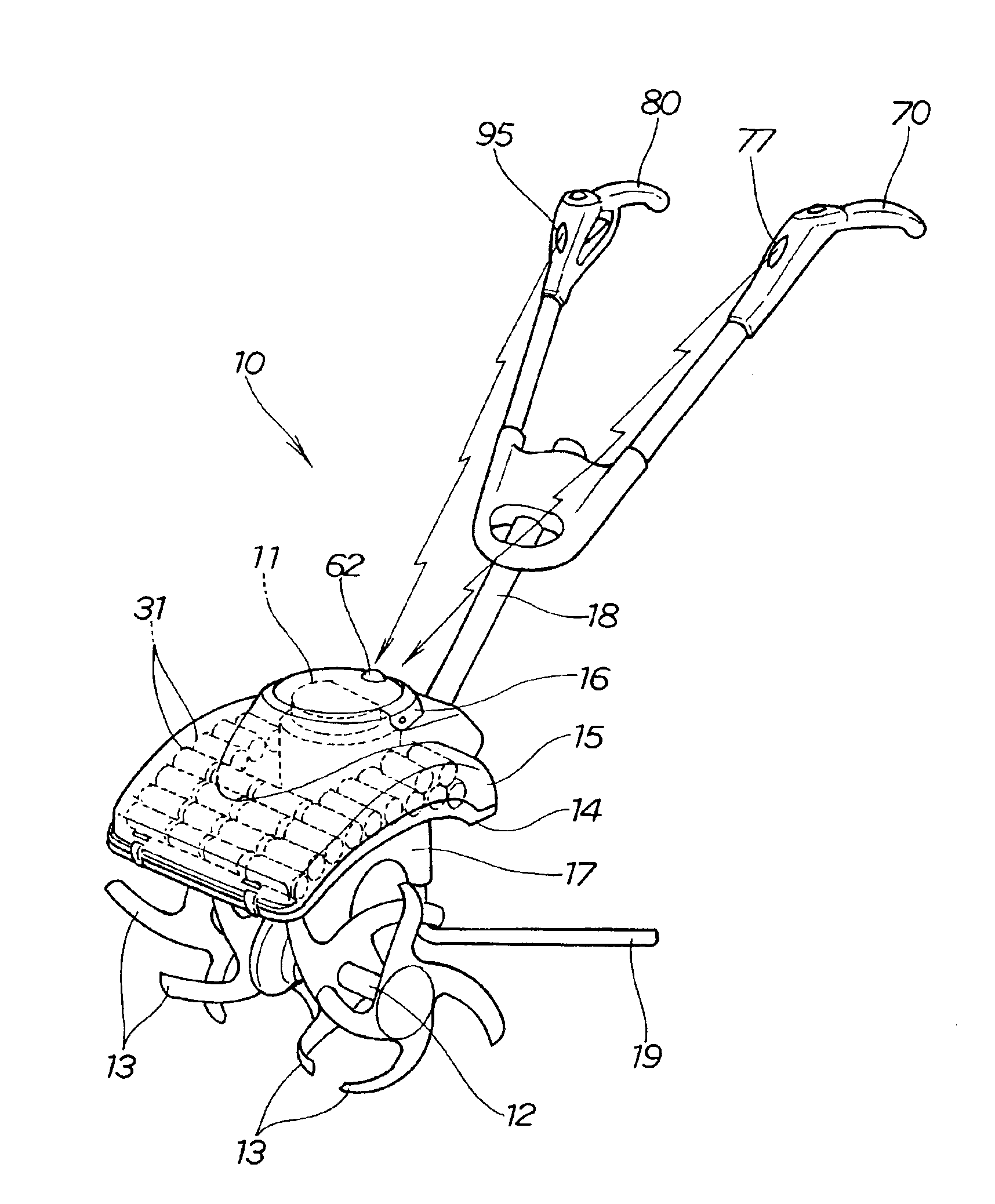
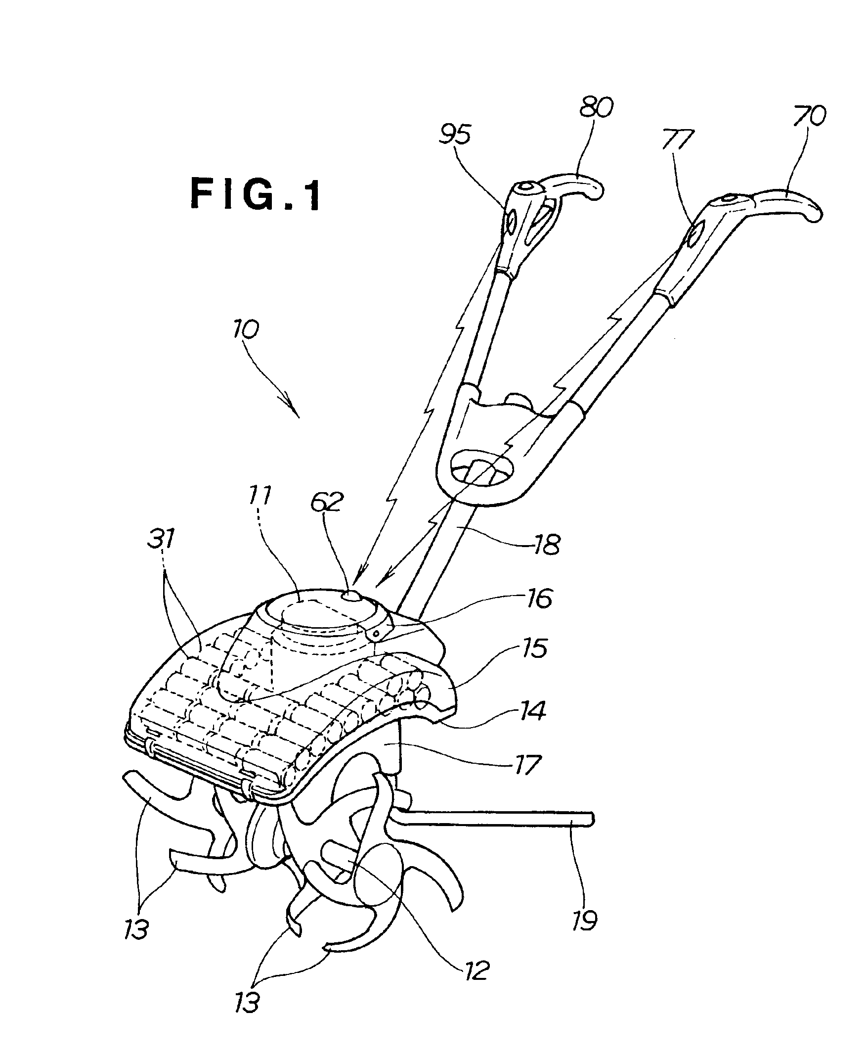
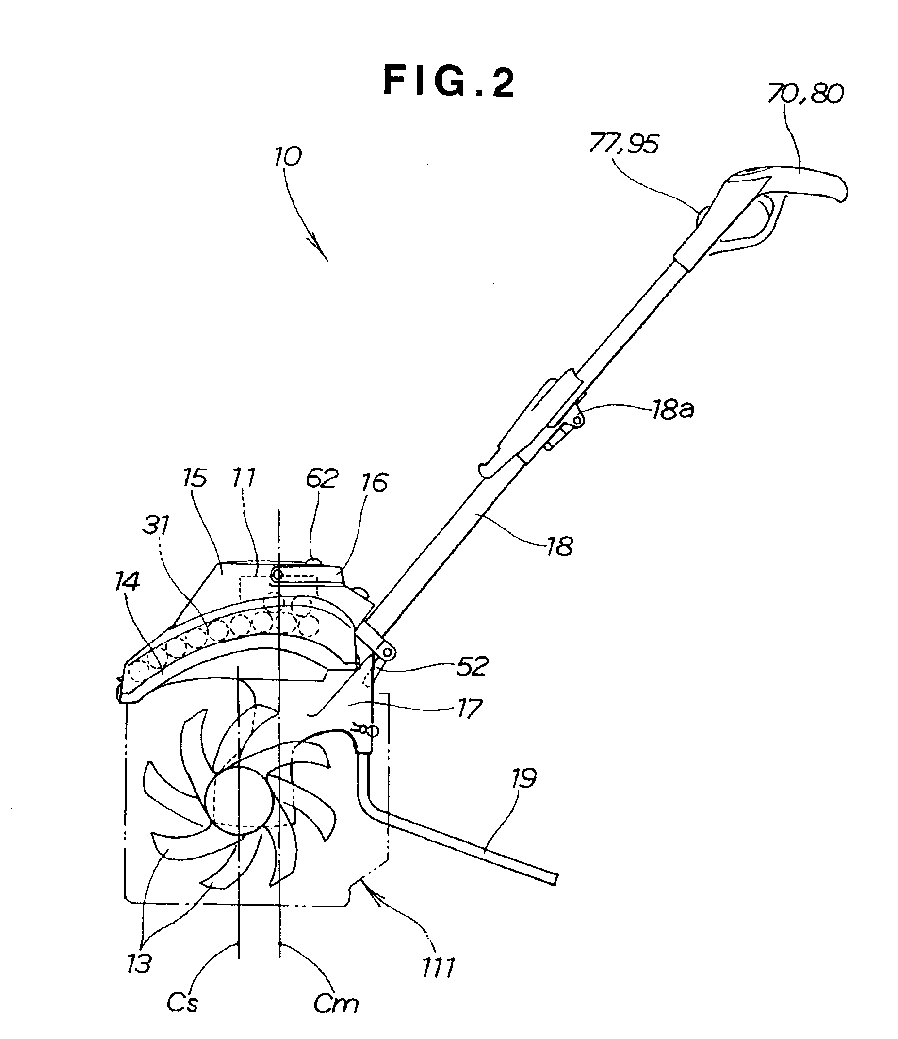
[0033]Reference is now made to FIGS. 1-7 showing a walk-behind electric cultivating machine according to an embodiment of the present invention.

[0034]The walk-behind electric cultivating machine 10 is a self-propelled, front-tine cultivating machine, which is constructed to transmit driving power from an electric motor 11 (i.e., drive source of the machine 10) to a cultivating shaft 12 so that the machine can travel on a field through rotation of a plurality of cultivating members in the form of cultivating claws 13 provided at left and right end portions of the cultivating shaft 12 while cultivating the field with the rotating cultivating claws 13. The cultivating claws 13 are covered with an upper fender 14, and an upper cover 15 covers an upper surface of the fender 14. The upper fender 14 and upper cover 15 define first and second cover members. respectively, forming an enclosure having an interior space Sp for housing the electric motor 11 and batteries 31 for supplying electri...


PUM


Abstract

A walk-behind electric cultivating machine has a body frame, an electric motor mounted on the body frame and having a motor shaft, and batteries mounted on the machine body frame for supplying electric power to the electric motor. Each of the batteries has a longitudinal axis disposed generally perpendicular to a longitudinal centerline of the motor shaft. A cultivating shaft is rotatably mounted to the machine body frame and has cultivating members mounted on the cultivating shaft for rotation therewith. A transmission mechanism is mounted on the body frame and is connected to the motor shaft for transmitting a driving power of the electric motor to the cultivating members via the cultivating shaft.

Description

FIELD OF THE INVENTION[0001]The present invention relates to walk-behind electric soil cultivating machines driven by electric motors.BACKGROUND OF THE INVENTION[0002]Ordinary walk-behind (soil) cultivating machines are also called “front-tine cultivating machines”, and such front-tine cultivating machines are constructed to transmit driving power from a drive source, such as an engine, to a cultivating shaft so that the machine can travel on a field through rotation of cultivating claws provided on the cultivating shaft while cultivating the field with the rotating cultivating claws. Advanced front-tine cultivating machines have been developed which employ an electric motor as the drive source in place of the engine, so as to lessen burdens on a human operator by enhancing operability of the machine and achieve an enhanced working environment (see, for example, Japanese Patent No. 3182930 and Japanese Patent Laid-Open Publication Nos. HEI-6-98601 and HEI-10-136702).[0003]In the cul...

Claims


Application Information

Patent Timeline
Patent Type & Authority Patents(United States)
IPC IPC(8): A01B33/02A01B33/00B62D51/06
CPCA01B33/028
Inventor SASAOKA, MASAYUKIFUKUZUMI, YASUMI
Owner HONDA MOTOR CO LTD
Why Eureka
Try Eureka