
Metering blade suspension system

a suspension system and metering blade technology, applied in the direction of instruments, corona discharge, electrographic process, etc., can solve the problems of undesirable image artifacts, insufficient control over the distribution and thickness of liquid intermediate transfer layer, etc., to achieve the effect of optimum performance and negative effect of printed image quality

Inactive Publication Date: 2005-07-26
XEROX CORP
View PDF13 Cites 21 Cited by
  • Summary
  • Abstract
  • Description
  • Claims
  • Application Information

AI Technical Summary

Benefits of technology

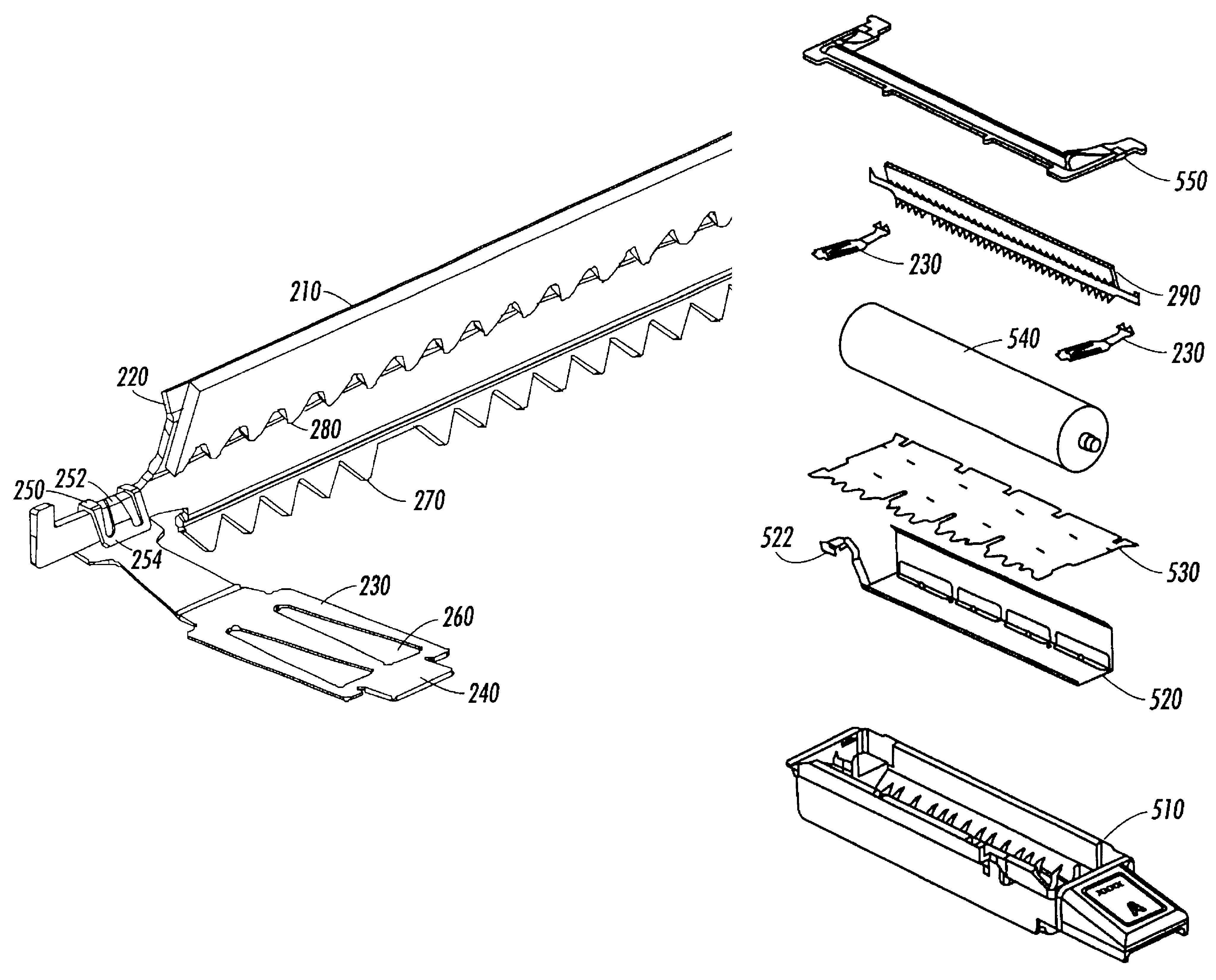
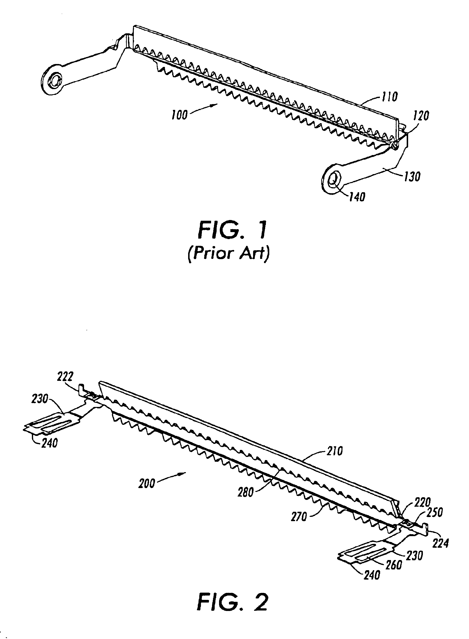
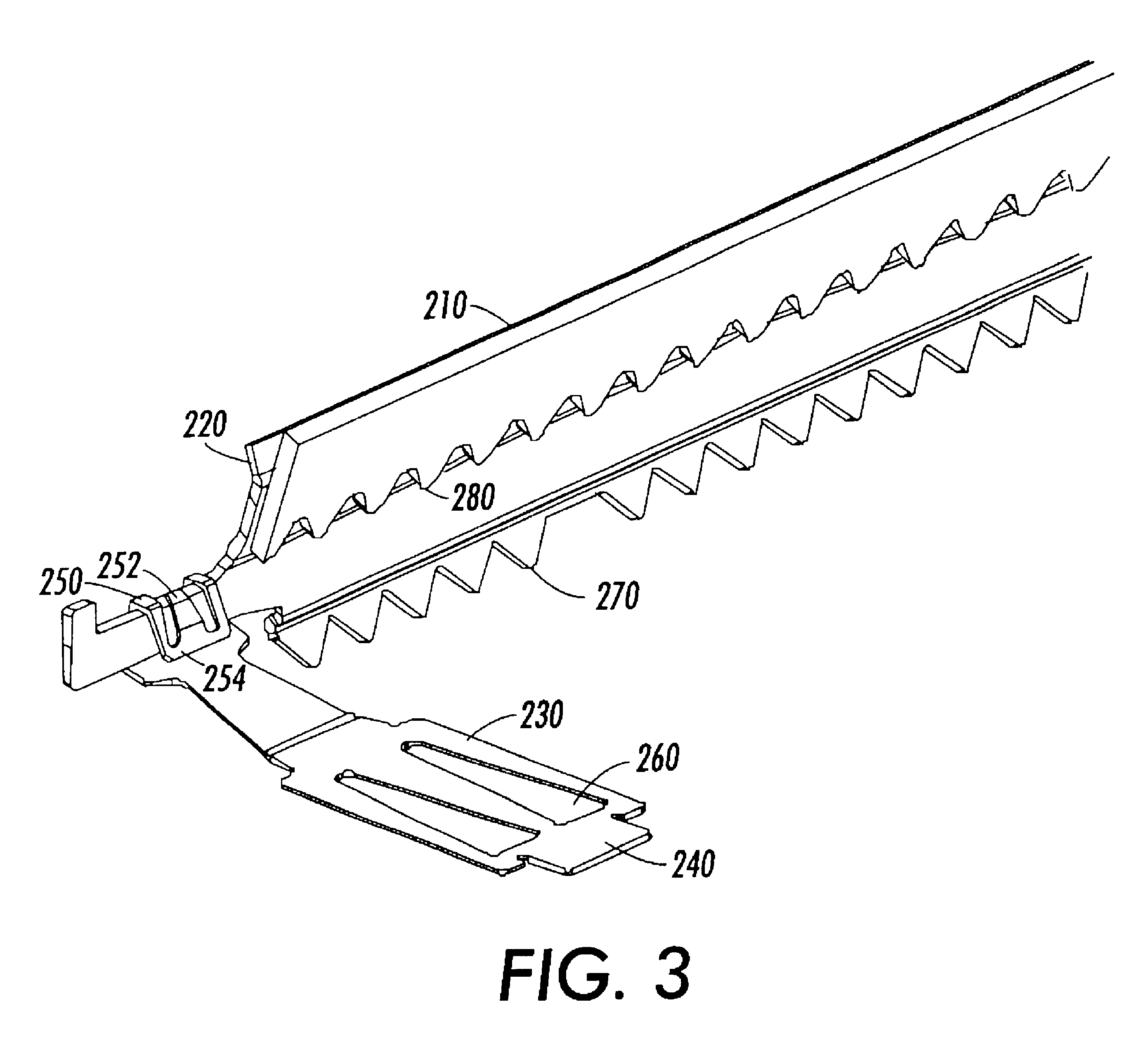
This patent describes a new ink printing system that uses a metering blade suspension system. This system is simpler and more reliable than previous designs, using fewer parts and reducing rotational friction. It also improves static discharge and reduces the size and cost of the drum maintenance unit. The system includes a leaf spring that controls the blade angle, position, and load, and may also serve as a grounding path for bleeding static charge. The patent also describes a drum maintenance unit that includes the metering blade assembly. Overall, this patent provides a more efficient and effective ink printing system.

Problems solved by technology

Insufficient control over the distribution and thickness of the liquid intermediate transfer layer has negative effects on printed image quality.
Non-uniform film distribution or improper film thickness around the imaging drum results in undesirable image artifacts.

Method used


Image

  • Metering blade suspension system
  • Metering blade suspension system
  • Metering blade suspension system

Examples


Embodiment Construction

[0027]This invention may be applied to various metering blade assembly configurations and is not limited to the particular configurations disclosed by the exemplary embodiments. Those skilled in the art will appreciate a metering blade suspension system in accordance with this invention without including all of the particular features disclosed by the exemplary embodiments.

[0028]FIG. 1 illustrates a conventional metering blade suspension system 100. A metering blade 110 is affixed to an elongated blade mounting bracket 120 that provides both a rigid support and arms 130 for rotation. Two torsion springs apply a load to bias the blade 110 against a drum (not shown). The arms 130 are provided at each end of the mounting bracket 120 and include an aperture 140 to facilitate the attachment of the mounting bracket 120 and to provide an axis of rotation. Typically, the metering blade 110 comprises an elastomeric material. As described above, the metering blade 110 functions to apply a fin...


PUM


Abstract

A metering blade suspension system utilizes a leaf spring that performs multiple combined functions such as supporting a metering blade assembly, controlling the angle, position and / or load of the blade assembly while allowing the assembly to pivot in a quasi-frictionless motion, locking the blade assembly in place, providing an electrical connection and / or bleeding static charge.

Description

BACKGROUND OF INVENTION[0001]1. Field of Invention[0002]This invention relates to a suspension system for a metering blade.[0003]2. Description of Related Art[0004]It is known to utilize intermediate transfer layers in ink printing systems, such as disclosed in U.S. Pat. Nos. 6,068,372 and 6,431,703, to Rousseau et al. These systems utilize an oiling roller that engages the imaging drum and applies a liquid intermediate transfer layer to the imaging drum. The print head ejects drops of ink onto the liquid intermediate transfer layer to form an ink image thereon. A receiving substrate such as paper is then brought into contact with the intermediate transfer layer on the imaging drum and the ink image is transferred to the receiving substrate.[0005]A part of the solid ink technology printing process includes the drum maintenance unit. One of the drum maintenance unit's objectives is to apply a metered amount of release agent to the imaging drum prior to the print head imaging process....

Claims


Application Information

Patent Timeline
Patent Type & Authority Patents(United States)
IPC IPC(8): F16F1/02F16F1/18F16F15/073
CPCF16F1/18F16F15/073G03G2215/06
Inventor ROUSSEAU, GERARD H.
Owner XEROX CORP
Learn More