Multi-piece vehicle wheel assembly

a vehicle wheel and multi-piece technology, applied in the direction of disc wheels, vehicle components, rolling resistance optimization, etc., can solve the problems of reducing the overall performance of the assembly, and increasing the weight of the rim, so as to reduce the mass of the wheel and the rotational inertia. , the effect of improving the vehicle performan

Inactive Publication Date: 2005-07-26
SMYTH LARRY C
View PDF17 Cites 11 Cited by
  • Summary
  • Abstract
  • Description
  • Claims
  • Application Information

AI Technical Summary

Benefits of technology

[0005]Therefore, it is an object of the invention to provide a multi-piece vehicle wheel assembly which improves vehicle performance by reducing both the wheel mass and its rotational inertia.
[0006]It is another object of the invention to provide a multi-piece vehicle wheel assembly which offers a unique rim and wheel styling potential.
[0007]It is another object of the invention to provide a multi-piece vehicle wheel assembly including a wheel center and rim which are quickly and conveniently attached by suitable fasteners.
[0008]It is another object of the invention to provide a multi-piece vehicle wheel assembly which removes inessential mass from the rim of the wheel.
[0009]It is another object of the invention to provide a reduced-mass, lightweight vehicle wheel rim.
[0013]According to another preferred embodiment of the invention, the inside major surface of the rim defines respective pockets between adjacent ones of the lands to reduce the overall weight of the rim.

Problems solved by technology

This added mass increases the weight of the rim and reduces the overall performance of the assembly as compared to conventional one-piece wheels.

Method used


Image

  • Multi-piece vehicle wheel assembly
  • Multi-piece vehicle wheel assembly
  • Multi-piece vehicle wheel assembly

Examples


Embodiment Construction

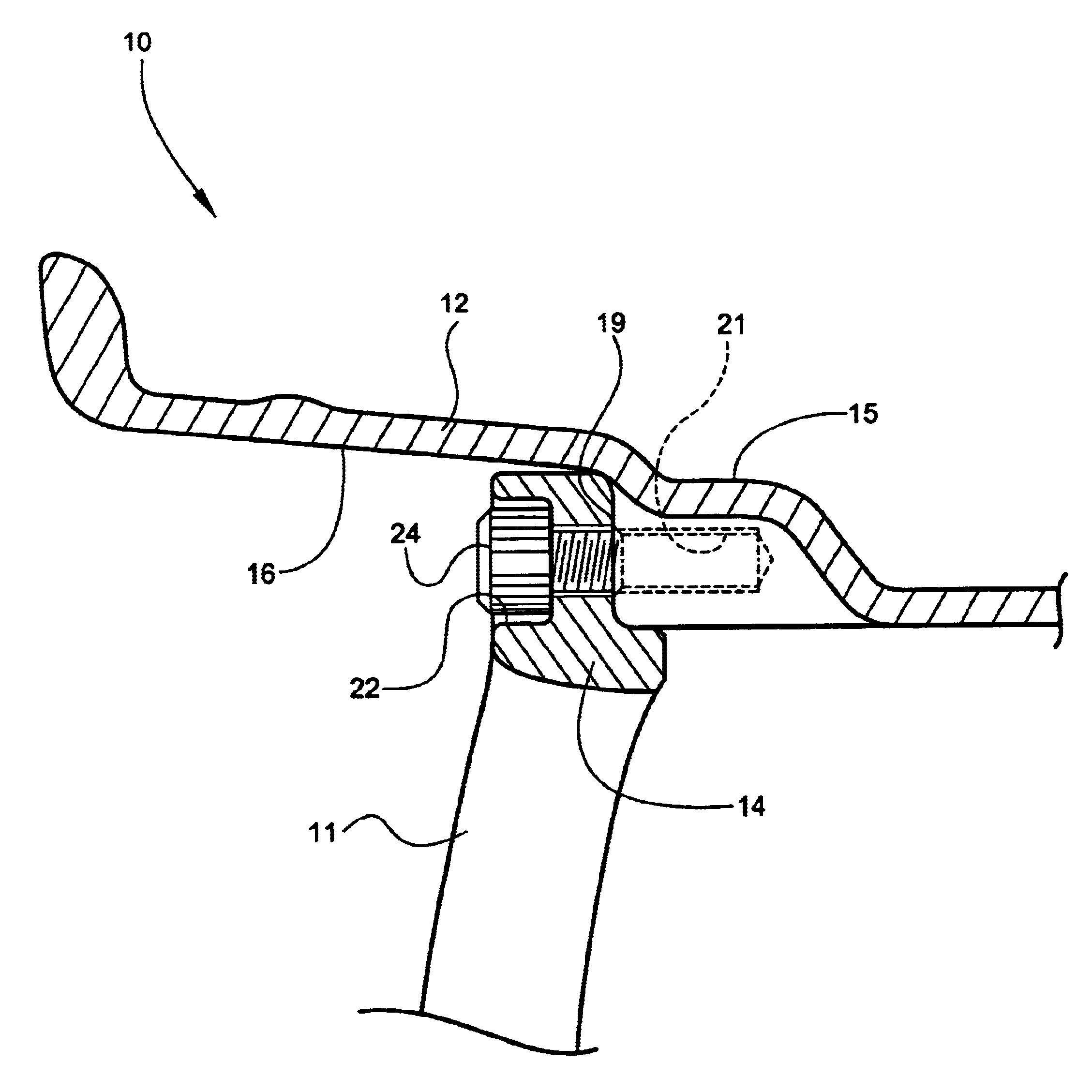
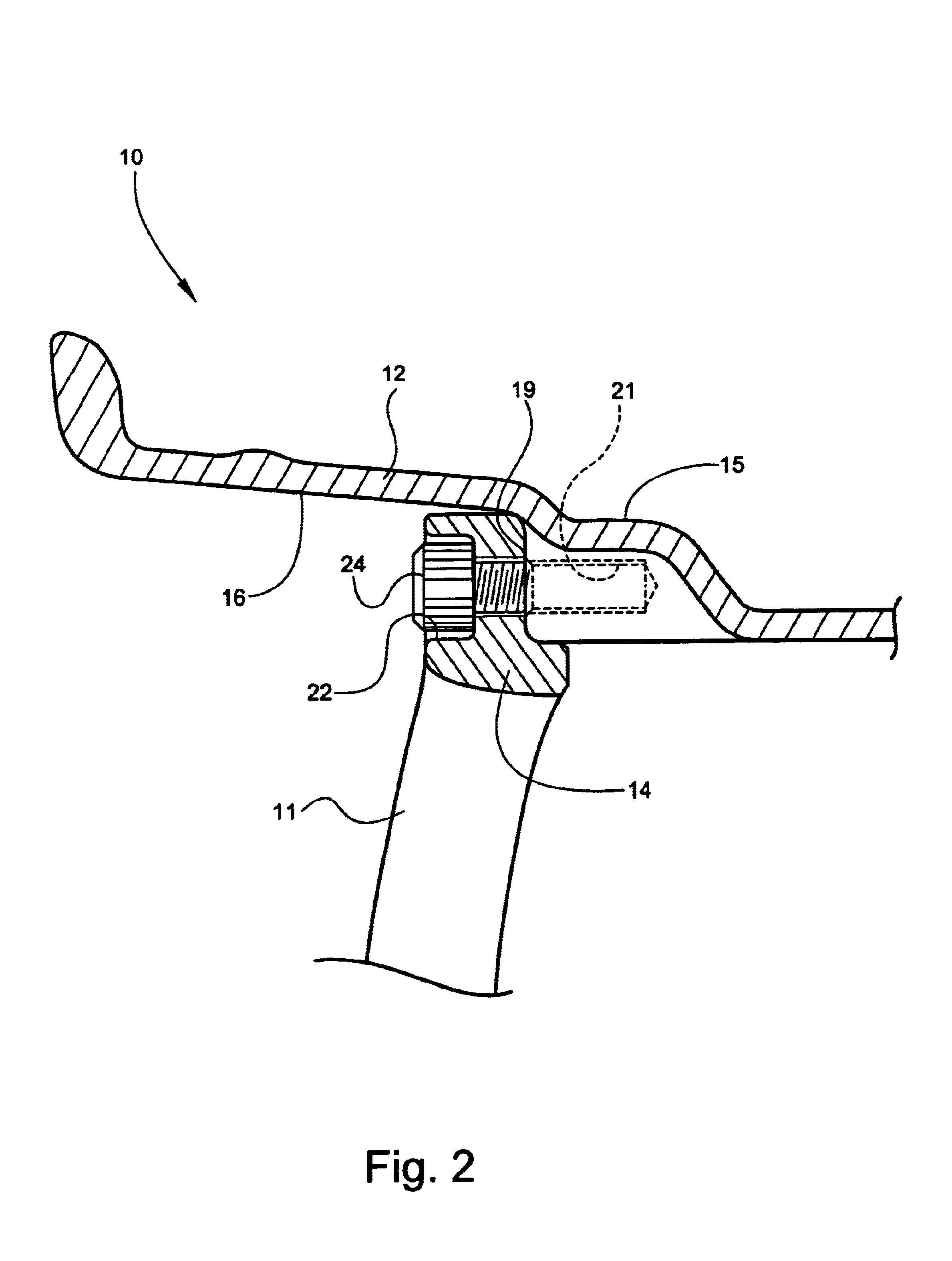
[0025]Referring now specifically to the drawings, a multi-piece vehicle wheel assembly according to the present invention is illustrated in FIG. 2, and shown generally at reference numeral 10. The wheel assembly 10 includes a wheel center 11 and rim 12. The wheel center 11 is formed in a conventional manner with a standard center hole for receiving wheel-mounting structure of the vehicle and an outer margin 14. In order to maximize the size of the wheel center 11, the diameter of the wheel center 11 is preferably slightly less than the outermost inner diameter of the wheel rim 12. A larger wheel center 11 promotes the aesthetics of the assembly 10.

[0026]Referring to FIGS. 2, 3, and 4, the wheel rim 12 has opposing outside and inside major surfaces 15 and 16. The outside major 15 surface defines a contoured rim bed for mounting the vehicle tire. The inside major surface 16 has a generally radially-extending annular shoulder 18. A number of circumferentially spaced rim bosses 19 are f...


PUM


Abstract

A multi-piece vehicle wheel assembly includes a wheel center and a lightweight wheel rim. The wheel center defines a center hole and has an outer margin. The wheel rim has opposing inside and outside major surfaces. The outside major surface defines a rim bed for mounting a vehicle tire. The inside major surface includes an inwardly-extending annular shoulder. A plurality of circumferentially spaced rim bosses are formed with the annular shoulder of the rim, and are adapted for engaging the outer margin of the wheel center. A corresponding plurality of circumferentially spaced fastener holes are formed along the outer margin the wheel center, and are adapted for aligning with the rim bosses formed with the rim. A plurality of fasteners are received through the aligned rim bosses and fastener holes to attach the rim and the wheel center together.

Description

TECHNICAL FIELD AND BACKGROUND OF THE INVENTION[0001]This invention relates to a multi-piece vehicle wheel assembly, and more specifically, to a wheel assembly incorporating a lightweight, reduced-mass aluminum alloy rim. The invention eliminates excess mass and inertia in an optimal multi-piece wheel construction applicable for both motor sport and normal road use.[0002]In an effort to create the optimal wheel, design engineers utilize complex computer simulations and expensive equipment to form a precisely accurate and highly efficient multi-piece structure. The optimal design must account for every gram of weight in the wheel as each gram generates extreme levels of force at high speeds. Moreover, because vehicle performance is improved by reducing both the wheel mass and its rotational inertia, it is especially advantageous to remove inessential mass from the rim of the wheel. The further away a given mass is removed from the wheel centerline, the greater the reduction in wheel ...

Claims


Application Information

Patent Timeline
Patent Type & Authority Patents(United States)
IPC IPC(8): B60B23/10B60B23/00B60B3/00B60B3/04
CPCB60B3/005B60B3/10B60B21/02B60B23/10Y02T10/86
Inventor SMYTH, LARRY C.
Owner SMYTH LARRY C
Why Eureka
Try Eureka