System and methods for reducing dust emissions

a technology of dust emission and dust capture, applied in the field of dust emission reduction systems, can solve the problems of creating and emitting dust particles, affecting the health of individuals, and affecting the general environment, so as to reduce dust emissions and reduce dust emissions

Inactive Publication Date: 2005-07-26
NIELSON CHAD J +1
View PDF18 Cites 7 Cited by
  • Summary
  • Abstract
  • Description
  • Claims
  • Application Information

AI Technical Summary

Benefits of technology

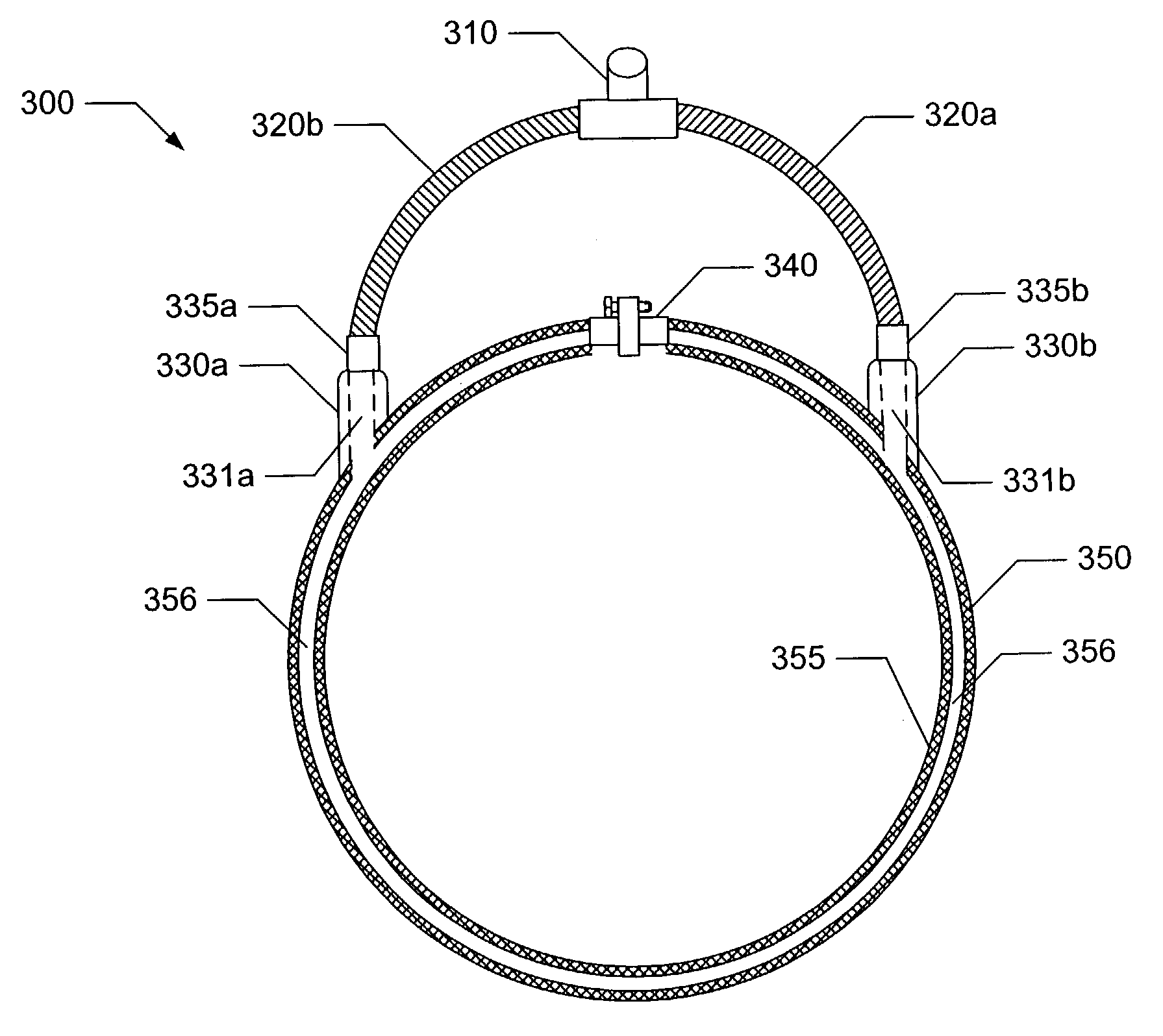
[0005]Some embodiments of the present invention provide methods for reducing dust emissions. Such methods can include providing an abrasion device that includes an abrasion surface with an outer perimeter. An abrasion device can be, but is not limited to, a hand sander, a hand buffer, a floor sander, a floor buffer, or the like. The abrasion element can be, but again is not limited to, a piece of sand paper, a buffing pad, a sanding wheel, or the like. The methods can further include attaching a dust catch to the abrasion device that includes an inlet. The inlet encompasses at least a portion of the outer perimeter of the abrasion element. Thus, for example, the inlet can surround the outer edged of a sanding or buffing wheel associated with a floor sander or floor buffer. As another example, the inlet can surround the outer edge of a piece of sand paper attached to a hand sander. In some cases, the inlet surrounds only a portion of the perimeter, while in other cases, the inlet surrounds the entire perimeter. In addition, the dust catch can include a discharger. This discharger can be, for example, a vacuum that can move dust near the inlet away from the inlet. The abrasion device can be operated, and at least a portion of the dust generated by operating the abrasion device is captured by the dust catch. In some cases, capturing the dust includes moving the dust from central areas of the abrasion surface to the periphery. This can include generating a vacuum in the inlet that moves dust particles near the inlet away from the inlet.
[0006]Some embodiments of the present invention provide methods for reducing dust emissions. Such methods can include providing an abrasion device that includes an abrasion surface with an outer perimeter. An abrasion device can be, but is not limited to, a hand sander, a hand buffer, a floor sander, a floor buffer, or the like. The abrasion surface can be, but is not limited to, a piece of sand paper, a buffing pad, a sanding wheel, or the like. The abrasion surface can move in relation to the abrasion device. Such movement can be, for example, rotational, vibrational, linear, or any combination thereof. The methods can further include attaching a dust catch to the abrasion device that includes an inlet. The inlet encompasses at least a portion of the outer perimeter of the abrasion element. Thus, for example, the inlet can surround the outer edged of a sanding or buffing wheel associated with a floor sander or floor buffer. As another example, the inlet can surround the outer edge of a piece of sand paper attached to a hand sander. In some cases, the inlet surrounds only a portion of the perimeter, while in other cases, the inlet surrounds the entire perimeter. The dust catcher further includes a discharger. In some cases, the discharger is a vacuum that moves dust particles from the inlet to, for example, an accumulator. The abrasion device can be operated, and at least a portion of the dust generated by operating the abrasion device is captured by the dust catch.
[0010]In some instances, the system further includes a skirt forming an outer wall of the inlet. The skirt can include a dust barrier. The dust barrier can inhibit dust particles from escaping the periphery of an abrasion device to which the system is installed. Further, the dust barrier can comprise a group of brushes extending below the skirt and formed of a material strong enough to maintain a dust barrier and soft enough to avoid damaging a sanded object. Thus, for example, in a floor sanding operation, the brushes may be in contact with a floor being sanded and be sufficiently stiff to inhibit most dust particles from escaping the periphery of an abrasion device, without scratching or otherwise damaging the floor being sanded. In particular instances, the skirt is formed to fit a rotational floor sander, and the latch is operable to couple the skirt to the rotational floor sander. In yet other cases, the skirt includes a size adjustment element. The size adjustment element can be modifiable to adjust the size of the skirt, thus making the skirt amenable for attachment to one or more abrasion devices.

Problems solved by technology

A number of activities generate dust particles that can be generally harmful to the health of an individual performing the activities, and detrimental to the general environment where the activities are performed.
The use of sanders and / or buffers results in the creation of and emission of dust particles.
Further, respirators can be both uncomfortable to wear and costly to obtain.
In addition, the use of respirators and dust masks do not eliminate or reduce the amount of dust particulates that are expelled into the general environment through the use of buffers and / or sanders.
These dust particulates can coat windows and furniture creating a mess that is often difficult to clean up.

Method used


Image

  • System and methods for reducing dust emissions
  • System and methods for reducing dust emissions
  • System and methods for reducing dust emissions

Examples


Embodiment Construction

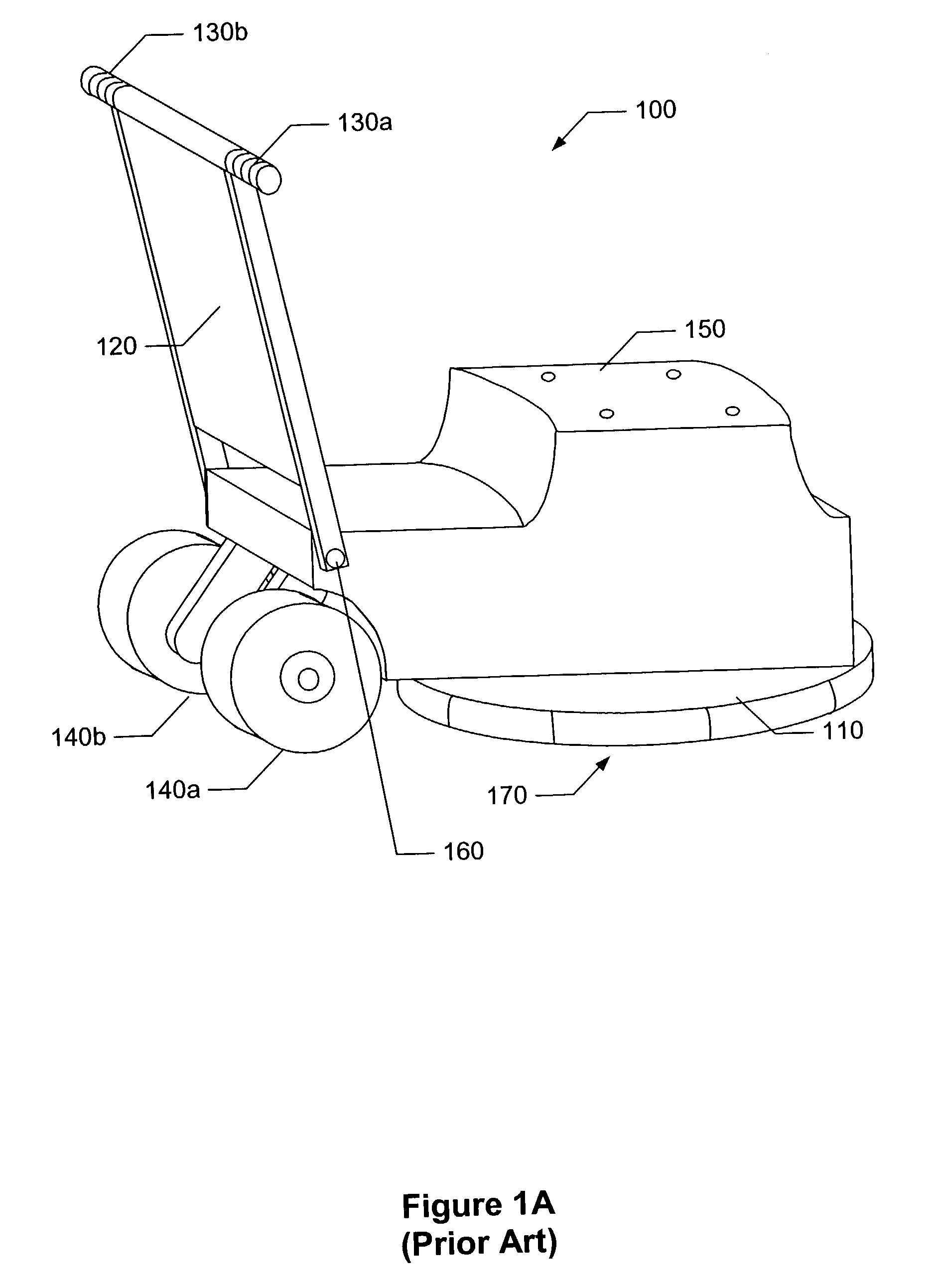
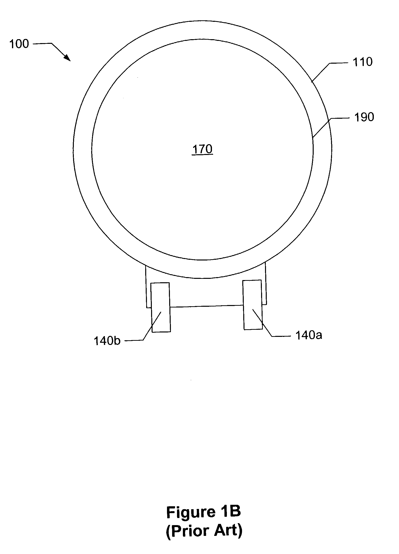
[0024]Dust reduction systems and methods useful in relation to a variety of systems and devices. Some of the systems include a dust catch disposed around the periphery of an abrasion surface and / or an abrasion device. The dust catch can include an inlet and a discharger. In some cases, the discharger includes a vacuum that pulls dust particles in through the inlet and expels the particles into an accumulator. In various cases, the inlet is placed such that it surrounds at least a portion of an abrasion surface and / or abrasion device so that when dust particles are expelled from the abrasion surface or abrasion device, they are captured at the inlet, and removed to an accumulator by a discharger. In some cases, the inlet surrounds less than a quarter of the perimeter of the abrasion surface, while in other cases, the inlet entirely surrounds the abrasion surface.

[0025]Turning to FIGS. 1a and 1b, a prior art floor sander 100 and / or buffer is illustrated. For the purposes of this docum...


PUM

PropertyMeasurementUnit
perimeteraaaaaaaaaa
sizeaaaaaaaaaa
areaaaaaaaaaaa

Abstract

The systems for reducing dust emissions include a dust catch. In some cases, the dust catch includes an inlet and a discharger. The inlet can be arranged so that it surrounds an abrasive surface of an abrasion device, such as a sander. Dust generated by the abrasion surface can be captured in the inlet and discharged by the discharger. In various cases, the inlet is associated with a skirt including a dust screen. The methods can include attaching a dust catch to an abrasion device such that an inlet of the dust catch encompasses at least a portion of an outer perimeter of an abrasion surface associated with an abrasion device. The abrasion device can then be operated and at least a portion of dust generated by operating the abrasion device is captured by the dust catch.

Description

BACKGROUND OF THE INVENTION[0001]This present invention provides systems and methods for reducing dust emissions. More particularly, the present invention relates to dust capture systems associated with abrasion devices, and methods of using such.[0002]A number of activities generate dust particles that can be generally harmful to the health of an individual performing the activities, and detrimental to the general environment where the activities are performed. For example, after installing wood flooring, the flooring is sanded, finished, and buffed. The processes of sanding and buffing involve the use of sanders and / or buffers. The use of sanders and / or buffers results in the creation of and emission of dust particles. To avoid the health hazards associated with such dust particles, an individual operating the sander or buffer often wears some form of respirator or dust mask. While the use of respirators and / or dust masks reduces the amount of dust particles that are inhaled, some...

Claims


Application Information

Patent Timeline
Patent Type & Authority Patents(United States)
IPC IPC(8): B24B1/00B24B23/00B24B7/18B24B55/10
CPCB24B7/186B24B23/00B24B55/102
Inventor NIELSON, CHAD J.NIELSON, LAWRENCE G.
Owner NIELSON CHAD J
Why Eureka
Try Eureka