Remote non-invasive biofeedback diagnostic system based on patient image

a biofeedback and patient image technology, applied in the field of remote biofeedback medical diagnostic system, can solve problems such as inability to find diagnostic methods, and achieve the effect of accurate diagnosis

Inactive Publication Date: 2005-07-26
CLINICTECH
View PDF13 Cites 16 Cited by
  • Summary
  • Abstract
  • Description
  • Claims
  • Application Information

AI Technical Summary

Benefits of technology

[0014]It is another object of the present invention to provide a remote diagnostic system capable of inducing the heightened state of consciousness in the operator so that his intuition is enhanced for a more accurate diagnosis.
[0015]It is a further object of the present invention to provide a remote diagnostic system capable of objective determination of the medical status of patient in general as well as his specific organs and even parts of organs and tissues.

Problems solved by technology

This diagnostic method is not available if the patient is located far from the diagnostic laboratory.

Method used


Image

  • Remote non-invasive biofeedback diagnostic system based on patient image
  • Remote non-invasive biofeedback diagnostic system based on patient image
  • Remote non-invasive biofeedback diagnostic system based on patient image

Examples


Embodiment Construction

[0023]A detailed description of the present invention follows with reference to accompanying drawings in which like elements are indicated by like reference letters and numerals.

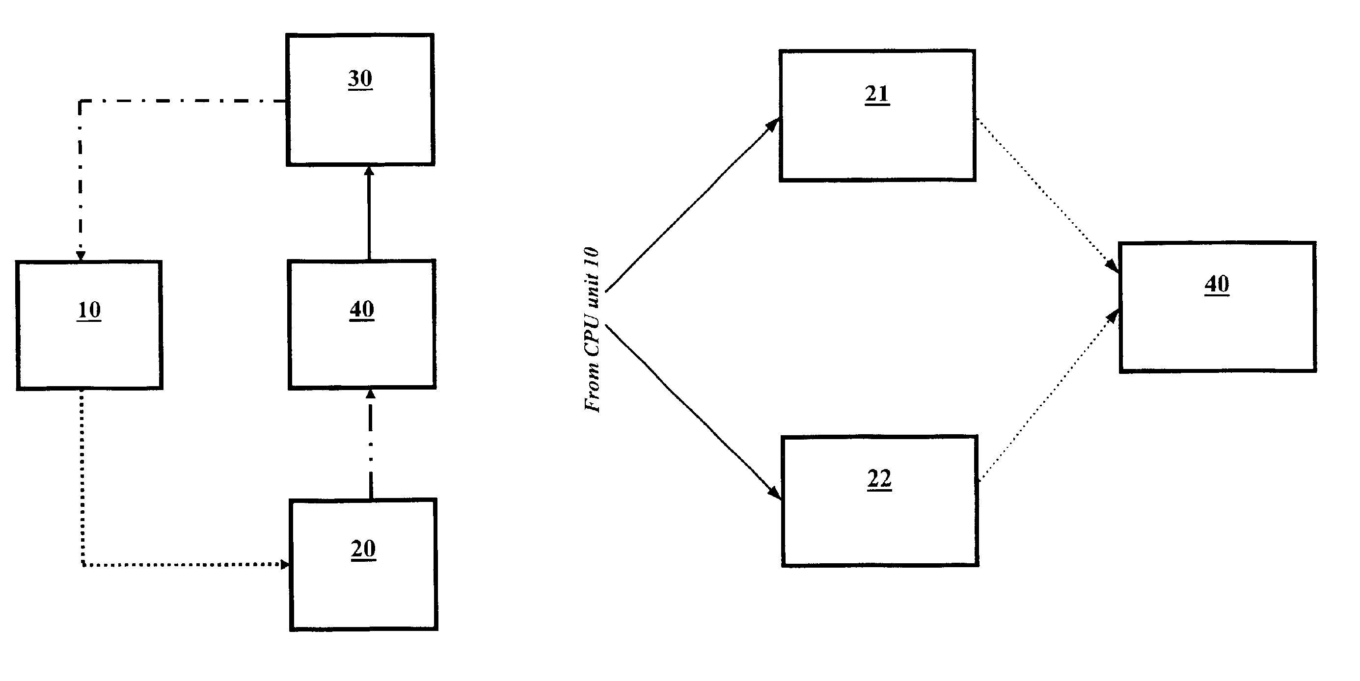
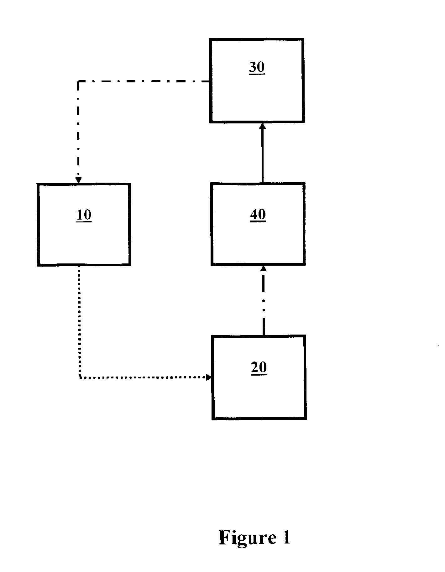
[0024]FIG. 1 shows the main block-diagram of the proposed system of the present invention, its components and their relationship to each other. A CPU unit 10 is a server computer and contains a situation-generating sub-system in a computer readable memory similar to that described in the U.S. Pat. No. 6,549,805 assigned to the same assignee as the present invention and incorporated herein by reference in its entirety. It is designed to output a predetermined patient-specific series of visual images and transmit them through CIU unit 20 to operator 40. CPU unit 10 is also connected to DEU unit 30 to receive electric biofeedback signals therefrom. These signals are stored in database system of CPU unit 10.

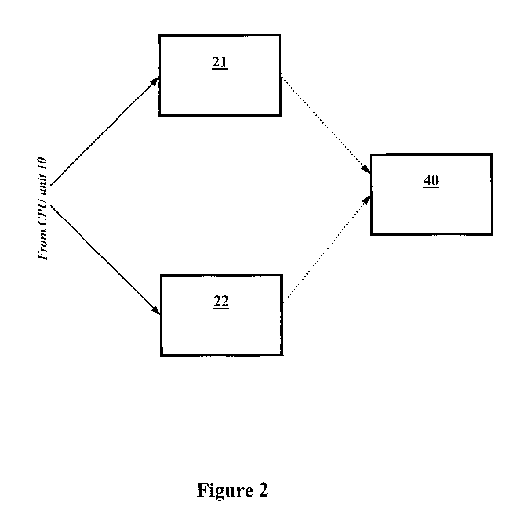
[0025]The main principle of the diagnostic system of the invention is to expose the operator to two sets o...


PUM


Abstract

A non-invasive remote diagnostic system includes a central processing unit (CPU) adapted to feed an image of a patient such as a digital photograph to be displayed to an operator by a first computer monitor. A second computer monitor is displaying a realistic outline of a target area of diagnostic interest such as an outline of a human organ or a particular portion thereof. These two monitors together with a CPU are adapted to induce a state of heightened consciousness and intuition of a system operator. A detecting / evaluating unit is sensing non-invasively the operator's biofeedback response while the operator is exposed to the images. The biofeedback response is converted to an electrical signal and is fed back into the CPU to compare against a predetermined database of similar signals obtained from volunteers with known diseases. The biofeedback signal allows a non-invasive remote diagnosis of a patient's state of health.

Description

FIELD AND BACKGROUND OF THE INVENTION[0001]The present invention relates generally to a remote biofeedback medical diagnostic system. More particularly, the system of the invention utilizes a noninvasive biofeedback signal obtained by the system from the operator exposed to the images of the patient and the target area to determine pathological conditions of the patient. The term “operator” is used interchangeably with the term “user” throughout this description to describe a human person using the biofeedback system. The biofeedback signal is generated subconsciously by the operator and is based on device enhanced intuition.[0002]A variety of medical diagnostic systems based on biofeedback are known in the art to determine the patho-physiological status of the patient in general and to diagnose a variety of ailments or the condition of specific organs.[0003]One example of a comprehensive biofeedback device is described by Schweizer in the U.S. Pat. No. 4,195,626 and includes applic...

Claims


Application Information

Patent Timeline
Patent Type & Authority Patents(United States)
IPC IPC(8): A61B5/00A61B5/16A61B5/0484A61B5/0476G16H30/20G16H30/40G16H40/67
CPCA61B5/16A61B5/486G06F19/321G06F19/3418A61B5/04842Y10S128/905G16H30/40G16H30/20G16H40/67A61B5/378
Inventor LEE, HANMYUNG
Owner CLINICTECH
Why Eureka
Try Eureka