Method of locally heating a part to reduce strength and increase ductility for subsequent manufacturing operation

a technology of local heating and workpiece, applied in the direction of heat treatment equipment, manufacturing tools, furnaces, etc., can solve the problems of manufacturing problems, adverse effects on certain manufacturing processes, and use of self-piercing rivets

Inactive Publication Date: 2005-07-26
FORD GLOBAL TECH LLC
View PDF9 Cites 19 Cited by
  • Summary
  • Abstract
  • Description
  • Claims
  • Application Information

AI Technical Summary

Benefits of technology

[0010]According to one aspect of the present invention, a method of manufacturing a metal workpiece is provided wherein a local area of the workpiece is heated. The workpiece is subsequently loaded into a tool and a force is applied with the tool that plastically deforms the local area that was previously heated in a desired manner. The workpiece is then unloaded from the tool. The metal workpiece may be formed initially of a heat treated high strength alloy material such as aluminum, iron, or magnesium alloy.

Problems solved by technology

There are many advantages relating to the use of high strength alloy materials but manufacturing problems may arise as a result of difficulties encountered when conventional manufacturing techniques are used with such materials.
Certain manufacturing processes may be adversely impacted when applied to high strength materials.
For example, the use of self-piercing rivets, attachment of clinch-type fasteners, hydro-forming, and magnetic pulse joining is more difficult when applied to high strength alloys such as heat treatable aluminum, steel, and magnesium alloys.
For example, lightweight aluminum self-piercing rivets are not normally useable with high strength alloys because of the hardness of such materials even though their use would allow for weight savings.
High strength materials are generally more brittle than conventional materials and alloys.
Brittle materials may crack during manufacturing processes due to limited ductility and may also suffer from material fatigue.
Manufacturing processes such as hydro-forming are limited when applied to high strength materials.
The use of high strength alloys in one or both of the materials may make it more difficult or limit the use of magnetic pulse welding in certain manufacturing operations.

Method used


Image

  • Method of locally heating a part to reduce strength and increase ductility for subsequent manufacturing operation
  • Method of locally heating a part to reduce strength and increase ductility for subsequent manufacturing operation

Examples


Embodiment Construction

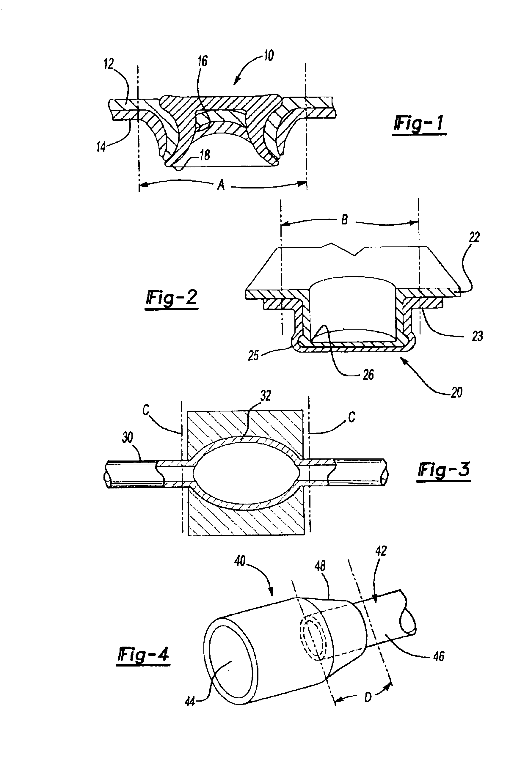
[0021]Referring now to FIG. 1, a self-piercing rivet 10 is shown joining first and second panels 12 and 14 together. The first and second panels 12 and 14 have a local area that is heated between the phantom lines A. The area between the lines A is heated preferably by induction heating or possibly by a flame torch to reduce the strength and increase the ductility of the material in the local area. The self-piercing rivet 10 is then inserted through the first and second panels 12 and 14 piercing them to form a hole 16 as the self-piercing rivet 10 is driven through the first and second panels 12 and 14. A swagged end 18 is formed to lock the panels together.

[0022]Referring now to FIG. 2, a clinch joint 20 is shown for securing two panels 22, 23, or two parts together. The clinch joint is formed in the panels 22, 23. One or both of the panels 22, 23 are heated in a local area surrounding the clinch joint 20 generally between phantom lines B. During the clinch assembly process, interl...


PUM

PropertyMeasurementUnit
strengthaaaaaaaaaa
ductilityaaaaaaaaaa
forceaaaaaaaaaa

Abstract

A method of performing manufacturing operations on a workpiece made of a high strength alloy is disclosed in which a local area of a workpiece is heated to micro-structurally soften the local area. The local area of the workpiece becomes softened and more ductile. A manufacturing operation involving deformation of the heat softened area is performed with the metal in the heat softened region being more ductile and having less strength than the surrounding portions thereof. Manufacturing operations may include riveting, clinching, hydro-forming, and magnetic pulse joining.

Description

BACKGROUND OF INVENTION[0001]1. Field of the Invention[0002]The present invention relates to micro-structural softening of a workpiece to improve manufacturing process performance.[0003]2. Background Art[0004]Manufacturing processes involve modification of workpieces and assembling workpieces. New high strength alloys are being implemented in manufacturing operations to take advantage of high strength to weight ratio of such materials. There are many advantages relating to the use of high strength alloy materials but manufacturing problems may arise as a result of difficulties encountered when conventional manufacturing techniques are used with such materials.[0005]Certain manufacturing processes may be adversely impacted when applied to high strength materials. For example, the use of self-piercing rivets, attachment of clinch-type fasteners, hydro-forming, and magnetic pulse joining is more difficult when applied to high strength alloys such as heat treatable aluminum, steel, and ...

Claims


Application Information

Patent Timeline
Patent Type & Authority Patents(United States)
IPC IPC(8): B21D26/02B21D39/03B21D26/00B21J15/00B21J15/08B21J15/02
CPCB21D26/023B21D26/059B21D39/031B21D39/034B21J15/025B21J15/08
Inventor JOAQUIN, ARMANDO MATEOSANDERS, PAUL GEORGE
Owner FORD GLOBAL TECH LLC
Why Eureka
Try Eureka