
Chemical reactor

a chemical reactor and reactor technology, applied in the field of chemical engineering, can solve problems such as imposing practical limitations on the size of panels

Inactive Publication Date: 2005-07-26
MEGGIT (UK) LTD
View PDF28 Cites 52 Cited by
  • Summary
  • Abstract
  • Description
  • Claims
  • Application Information

AI Technical Summary

Benefits of technology

[0018]Preferably the heat exchanger panel is entirely of the printed circuit heat exchanger type (PCHE), and at least two differing plate designs are used to make up the panel whereby substantial variation in flow path design is achievable. Primarily, the direction of flow of fluids in the PCHE panel is initially established by the respective feed and vent connections to inlet and outlet ports of the assembled PCHE plates constituting the panel. However by altering the “printed circuit” style design of the flow path in the plates, to provide differing PCHE plates within the panel, it is possible to control both flow path direction and influence rate of heat transfer.
[0019]Use of plates of differing design is a preferred option for flexibility in design choice, but in certain cases use of plates of substantially the same design can be adopted. In the special case of identical square plates juxtaposed in a stack, each having a particular pattern of passages etched out on the surface thereof, passages in different orientations can be defined by rotating alternate plates in the plane of the plate, and optionally interposing plates having no etched surfaces (blanks) where necessary to prevent intermixing of fluids. In this fashion, a succession of flow paths in differing directions can be achieved.
[0023]According to one aspect of the present invention there is provided apparatus of the staged adiabatic reactor type including a chemical reaction zone bounded by at least one surface including means for achieving heat exchange with fluids flowing via said zone to achieve a reaction, said zone and said surface at least in part being defined by a printed circuit heat exchange (PCHE) panel, said panel defining discrete passages providing for flow of fluid reactants and a heat transfer medium, wherein at least two different flow paths are defined by the PCHE plate design for handling the heat transfer medium, whereby said heat transfer medium is permitted to pass in at least two differing directions with respect to the flow of fluid reactants via the PCHE panel and thereby particularly provide for improved control of the reactant temperature profile of fluids passing out of the PCHE panel.
[0027]According to another aspect of the invention there is provided a process for performing chemical reactions under controlled temperature conditions, preferably in reactors of the staged adiabatic type, and comprising, delivery of fluid reactants successively via a chemical reaction zone to achieve a reaction and heat exchanger means, said zone being bounded by at least one surface including means for achieving heat exchange with said fluids, said surface at least in part being defined by a printed circuit heat exchanger (PCHE) panel providing means defining discrete passages providing for flow of a heat transfer medium therein, and further passages providing for flow of reactant fluids, introducing heat transfer medium to said PCHE panel, and causing same to pass in at least two differing directions with respect to the flow of fluid reactants via said PCHE panel to provide for improved control of the reactant temperature profile of fluids passing out of the PCHE panel.
[0030]According to another aspect of the invention, a PCHE plate design consists of multiple flow passages following serpentine paths essentially in parallel and exhibiting sharp changes in direction within the serpentine path e.g. by having a zig-zag pattern imposed upon substantially the whole length of each individual passage. The number of serpentine turns in each path is variable but at least 2 turns are needed to provide a return pass and an exit pass. The use of a zig-zag design is an optional feature. Primarily the advantage of the convoluted flow passage arrangement lies in providing a fluid path flow length which is an even or non-integral multiple of the flow length, permitting a better match of heat transfer and pressure drop requirements.

Problems solved by technology

However, it will be appreciated that the dimensions of the heat exchanger unit will vary according to a chosen reactor design, and that currently available manufacturing equipment may impose some practical limitations on panel size in one step.

Method used


Image

  • Chemical reactor
  • Chemical reactor
  • Chemical reactor

Examples


Embodiment Construction

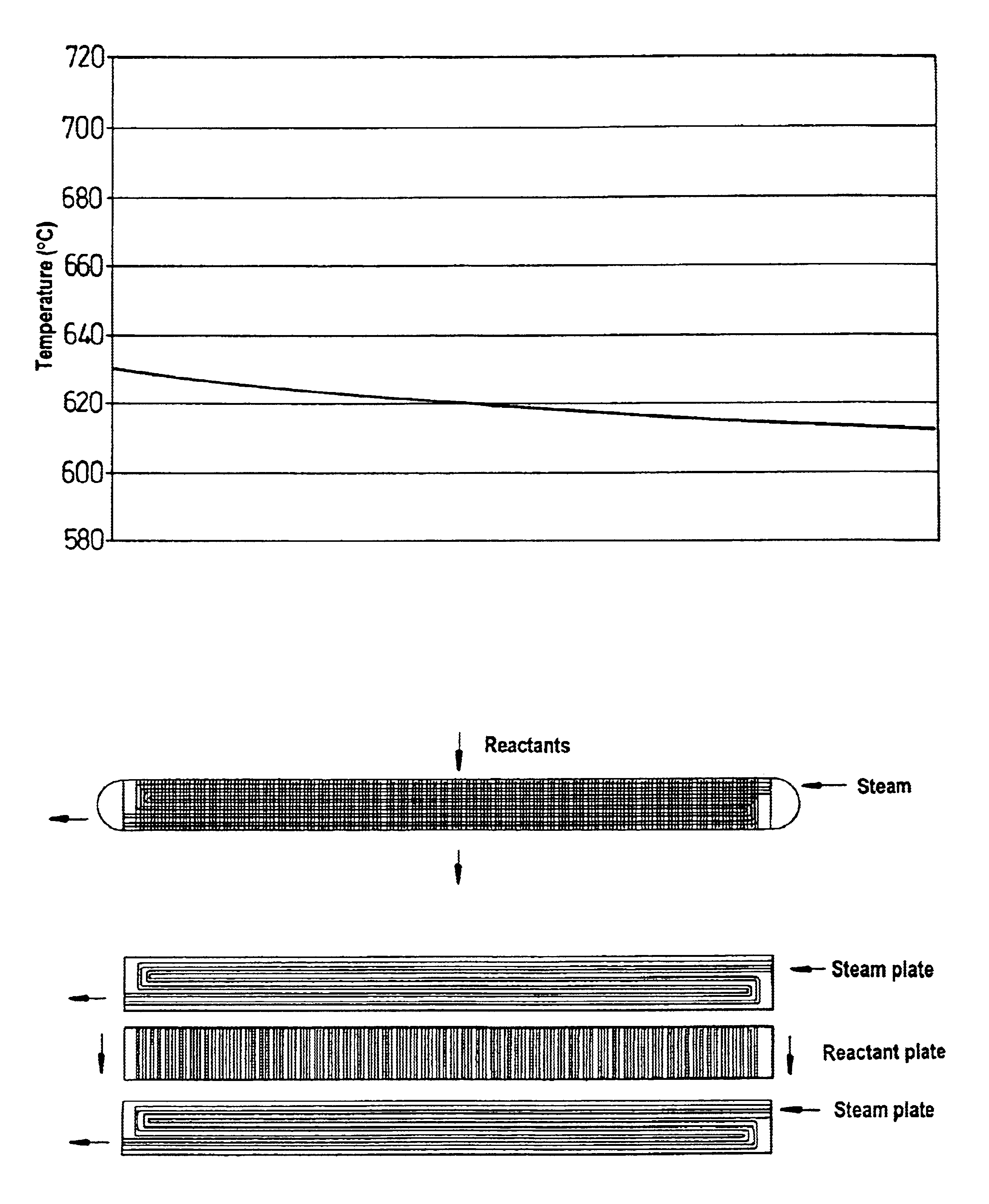
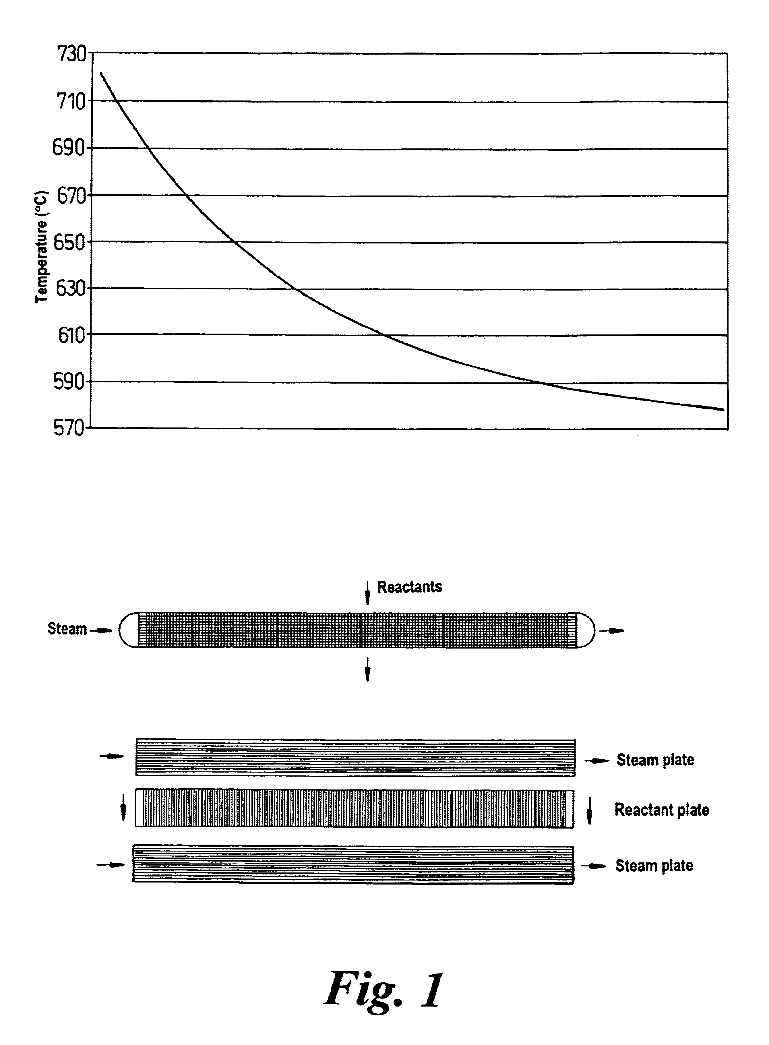
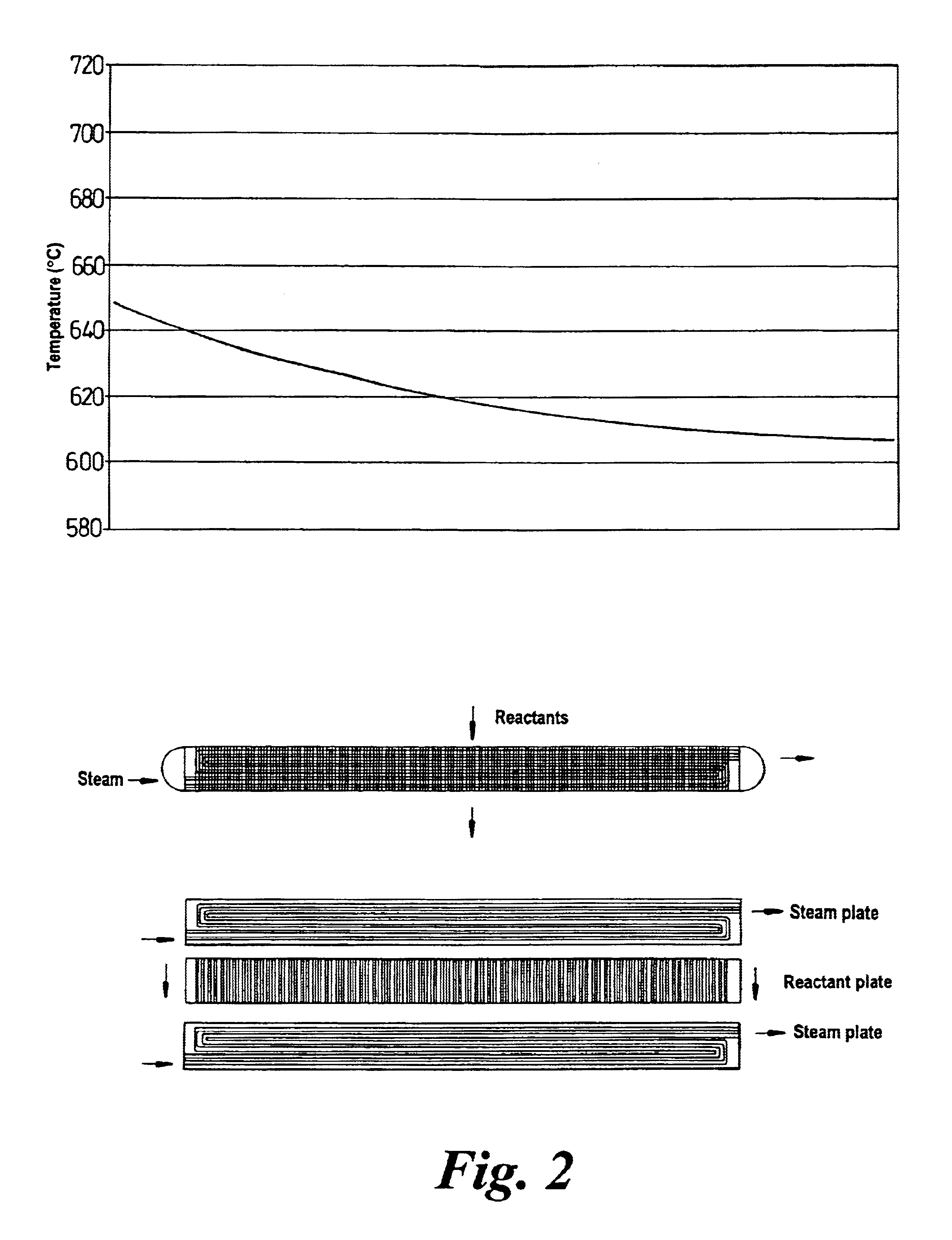
[0043]An improved catalytic reactor system is obtainable according to the invention by use of PCHE panels arranged therewith to obtain a substantially flat reactant temperature profile upon exit from the PCHE in comparison with prior art systems as will be described below, particularly with reference to the preferred embodiment of FIG. 6.

[0044]In this discussion, for convenience, designs in which the heat transfer medium enters at both sides of the PCHE panel are called “two-way” designs, and those in which the heat exchange medium enters only at one end of the PCHE panel are termed “one-way” designs.

[0045]FIG. 6 (lower part) illustrates schematically an arrangement for a PCHE panel 4 made up of plates for receiving heat exchange medium, here steam, of differing design 1, 2 each arranged either side of a reactant fluid-flow plate 3, firstly as the plates would be arranged in use and below that representation, with the plates separated for clarity in illustration of the respective fl...


PUM

PropertyMeasurementUnit
Lengthaaaaaaaaaa
Flow rateaaaaaaaaaa
Shapeaaaaaaaaaa

Abstract

A reactor of the staged adiabatic reactor type, comprises at least one heat exchanger panel, preferably a printed circuit heat exchange (PCHE) panel, interposes between adiabatic beds of catalyst, wherein the facial area of the panels and the superficial facial area of the corresponding catalyst are substantially similar, and the panels include means defining discrete passages for handling of reactants and heat transfer media, wherein the means defining passages for heat transfer media provide for at least two differing flow path directions for the heat transfer media through the heat exchanger panel whereby the occurrence of temperature bias or differentials is reduced.

Description

CROSS-REFERENCE TO RELATED APPLICATIONS[0001]This application claims priority under 35 U.S.C. §119(e) to U.S. Provisional Patent Application No. 60 / 184,007, entitled Catalytic Bed Reactor, filed Feb. 22, 2000, and under 35 USC §119(a) to G.B. 0001699.8, filed Jan. 25, 2000 and G.B. 0017188.4, fiIed Jul. 13, 2000, the entirety of each of which is incorporated herein by reference.FIELD OF THE INVENTION[0002]The present invention is applicable in the field of chemical engineering and especially relates to improvements in chemical reactors. In general the invention relates to control of the reactant temperature during an exothermic or endothermic reaction. Particularly the invention provides a printed circuit reactor (PCR) system and process control method wherein the reactant temperature profile at the exit of the heat exchanger panels is “flat”, i.e. the reactant exit temperature across the width of the heat exchange panel is ideally uniform and as near to constant as possible.BACKGRO...

Claims


Application Information

Patent Timeline
IPC IPC(8): B01J8/04B01J8/02B01J19/00C01C1/00C01C1/04
CPCB01J8/0221B01J8/0235B01J8/0285B01J8/0292B01J8/0438B01J8/0496B01J19/0013C01C1/0417B01J2208/0015B01J2208/00212B01J2208/00221B01J2219/00085B01J2219/182B01J2219/1943F28D9/0037F28F3/048F28F2260/00Y02P20/52
Inventor JOHNSTON, ANTHONY
Owner MEGGIT (UK) LTD
Learn More